Download
1 / 20
210 likes | 508 Vues
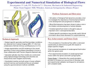
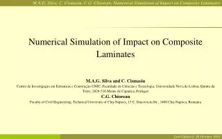
Numerical Simulation of Impact on Composite Laminates M.A.G. Silva and C. Cismasiu Centro de Investigaçao em Estruturas e Construção-UNIC, Faculdade de Ciências e Tecnologia, Universidade Nova de Lisboa, Quinta da Torre, 2829-516 Monte de Caparica, Portugal C.G. Chiorean

E N D
Numerical Simulation of Impact on Composite Laminates M.A.G. Silva and C. Cismasiu Centro de Investigaçao em Estruturas e Construção-UNIC, Faculdade de Ciências e Tecnologia, Universidade Nova de Lisboa, Quinta da Torre, 2829-516 Monte de Caparica, Portugal C.G. Chiorean Faculty of Civil Engineering, Technical University of Cluj-Napoca, 15 C. Daicoviciu Str., 3400 Cluj-Napoca, Romania Last Updated: 26 October 2014
Objectives • Numerical simulation of impact problems on composite • laminate plates reinforced with Kevlar 29/Epoxy. • Low velocity impact produced using Rosand Precision Tester. • Estimate the V50 and the global damage caused by a • STANAG-2920 projectile.
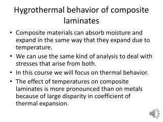
Material Model • The following phenomena may need to be modelled for composite materials under ballistic impact: • Material anisotropy • Shock response • Coupling of volumetric and deviatoric behavior • Anisotropic strength degradation • Material compaction • Phase changes
Advanced Orthotropic Model • An advanced model for orthotropic materials subjected to high and hypervelocity impact. • Features: • Couples the Non-Linear Equation of State and orthotropic stiffnes matrix • Compaction and orthotropic brittle failure criteria to detect directional failure initiation • Orthotropic post failure response in predicting delamination of fibre reinforced composite materials
Laminated Composite Model • Orthotropic Post-Failure Response for Orthotropic Materials • Dominated Failure Modes in Laminated Composites are: • Delamination caused by through thickness failure or shear failure in matrix • Tensile fibre failure- in plane failure of fibres • Combination of delamination and tensile fibre failure, leading to bulk failure • Equivalent orthotropic material properties Equivalent model-individual layers not represented explicit Laminated composite
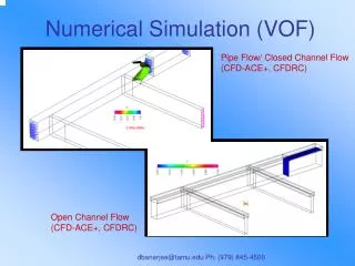
Impact Analysis • The interactive non-linear transient dynamics analysis software • Explicit finite difference techniques • Lagrange processor including erosion techniques • Advanced robust automatic dynamic contact logic • Orthotropic material models and extensive built-in materials database
Numerical Model Used in Low Speed Impact Simulation • The Lagrange processor was used for projectile and target • Uniform cells of side 1.25 mm were used in the central impact area • Interaction: impact-slide logic with a gap size 0.053 mm • Hourglass damping increased to 0.15 Target: Circular Kevlar 29 plate with radius of 50 mm and thickness 1.8 mm Projectile: Steel 4340 Sphere with radius 5 mm. Mass=3.867 kg
Deflection History Energy level 2J Energy level 5J Energy level 10J Energy level 20J
Maximum Deflection and Coresponding Peak Time Maximum error: 11% (E=2J) Minimum error: 2% (E=20J)
Maximum Impact Force and Coresponding Peak Time • The peak of the impact force was computed according to the Hertzian contact model. Maximum error: 18% (E=2J) Minimum error: 1,8% (E=20J)
Numerical Model Used in Ballistic Impact Model • The Lagrange processor was used for projectile and target • Uniform cells of side 0.4 mm were used in the central impact area • Degenerate cells eroded at an Instantaneous geometric strain 1.0 • Interaction: impact-slide logic with a gap size 0.014mm Target: Square Kevlar29/Epoxy plate, 100x100x2mm Projectile: STEEL 4340, STANAG-2920
Projectile: STANAG-2920, US-MIL-P-46593 0.98 5.42 5.30
Ballistic Limit: Impact at 320m/s-Total Damage Front view: Experimental vs. Simulation Results Delamination
Ballistic Limit: Impact at 320m/s-Total Damage Back view: Experimental vs. Simulation Results Fibre Failed Eroded Nodes
Ballistic Limit: Simulated Damage Development t=0.0178 ms t=0.0062 ms t=0.0270 ms Eroded nodes Delamination t=0.0356 ms t=0.0399 ms t=0.0434 ms
V50: Experiment vs. Simulated Total Damage Front view: Experimental vs. Simulation Results Delamination
V50: Experiment vs. Simulated Total Damage Back view: Experimental vs. Simulation Results Fibre Failed Eroded Nodes
Conclusions • Simulations of low and high speed impact of composite laminate platereinforced • with Kevlar29were performed. • Orthotropic constitutive relations coupled with a progressive directional damage • model to account for typical damage mechanism of laminates. • For low speed impact good corelation between numerical predictions and • experimental tests - deflections and impact force. • Numerical results stabilised and improved by increased of damping coefficient. • For high speed impact good corelation between numerical and experimental tests • both in terms of deformation and damage of the laminate and ballistic • performance.