Download
1 / 23
230 likes | 315 Vues
Summary of the informal testing conducted on search equipment's performance in real-world conditions by the WIPP RAP team. Factors, caveats, and results with detailed analysis provided.

E N D
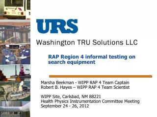
RAP Region 4 informal testing on search equipment Marsha Beekman - WIPP RAP 4 Team Captain Robert B. Hayes – WIPP RAP 4 Team Scientist WIPP Site, Carlsbad, NM 88221 Health Physics Instrumentation Committee Meeting September 24 - 26, 2012
Introduction • Purpose was to test overall performance for search equipment based on field conditions. • Intended to support team captain, leader, and scientist determinations for coupling equipment with particular missions.
FACTORS • Factors folded into evaluation were interface and interpretation of instrument response. • Conditions were windy and not compensated for in user interface (what you see is what you get) in outdoor clear conditions. • Direct sunlight may have caused reading difficulty on some displays • Users allowed to continually look at instrument if vibration alarms too difficult to discriminate while walking.
Caveats • We do not claim all other users will get identical results. • Our results are approximate at best. • Field conditions could substantially change the results of this test. • Instruments requiring continual visual monitoring may not be consistent with some mission parameters. • Each user came up with their own criteria
Caveats (cont.) • Results were generated by less than 20 experienced and trained users. • Performance by users with differing amounts of training and experience could substantially change these results. • Training effectiveness for individual units could substantially change these results. • Weather (daylight, wind, rain etc) could substantially alter results. • Only Cs137 source tested
PackEyeThermo Scientific • Alarm - LED indication, audio or earphone • Power supply NiMHRech., 3 days • Neutron detector 2 He-3 1.5”x2”, 2.5 atms. • Gamma detector NBR 50 keV to 3 Mev/>30 cps PackEye <13 lbs.
HRM (Handheld Radiation Monitor)(Sensor Technology Engineering, Inc.) • Alarm – Single digit (G N) LED indication and audio or vibrating alarm • Power supply - 3 Volt lithium (2/3A), 1month • Neutron detector • He-3, 8.3 atms., 0.75”x7.8” • Gamma detector • CsIscintillator, 0.5”x1.5” HRM 8.3”x 2”x1.2” <1 lb.
LRM • Alarm – LCD single digit (multi scaling), audio or vibrate • Power supply 3 volt lithium 2/3A 8 hrs. (backlight) 24 hrs. without • Neutron detector • Gamma detector Not actual LRM shown
D-tectD-tect Systems • Alarm LED, single digit • Power supply – 2 AA, 5,000 hrs. • Neutron - None • Gamma detector CsI(Na) 0.5” x 1.5” 30 keV – 3 MeV D-tect 3.9”x 2.7”x1.2” 6.4 oz.
G-N Pager Polimaster • Alarm audio and/or vibrate, dose rate/cps readout • Power supply AA, 800 hrs. • Neutron detector LiI(Eu) thermal to 14 MeV • Gamma detector CsI(Tl) 0.06 MeV to 3 MeV Unit (without clip) 3.4” x 2.8”x 1.2” 8 oz.
InterceptorTermo Scientific • Alarm LED dose rate/cps • Power supply Li-Ion rechargeable battery • Neutron detector He3, 8 atm., 0.5”x2.6” • Gamma detector CZT 0.3”x0.3”x0.15” 25 keV to 3 MeV ID with spectrum display Interceptor 4.8”x2.6”x1.2” 14 oz.
4 ft spacing 4 ft spacing 4 ft spacing 4 ft spacing 4 ft spacing Source Test Configuration • Track had source at 8 foot offset • Source was not neutron • Distance markers at 4 foot intervals out to 24 feet • Users told to simply operate equipment according to their training • all users experienced
Test implementation • Data recorded by independent user. • Not all measurements made on all instruments by all users. • No attempt was made to correct for user interface or interpretation of instrument response. • Data averaged over approach from both sides (instrument held on left and right sides).
Initial alarm performance • Multiple performance metrics of interest • First to alarm • Last to alarm • Most consistent performance (lowest s) • Results show (on average) comparable initial alarm distance on all units • D-Tect most consistent (reproducible) results
Maximum Alarm Position • Important in terms of specifically identifying source position (max. response at 0). • Results presented in distance from perpendicular projection of source (not total distance to source). • Some configurations can promote offset maxima • Interceptor best followed by the HRM, D-tect and then GN pager.
Alarm Clear Location • Quick alarm clear can be useful for identifying source location. • If alarm continues well after source closest approach, alarm utility is reduced. • Overall, instruments tend to alarm after the source . • Attributed to moving time window to update and pedestrian motion.
Discussion • Users tend to prefer items which do not require continual visual readout interpretation. • You need to watch where you are walking • Situational awareness can be critical • Instruments known to have the highest sensitivity had some performance issues due to interface and instrument interpretation. • For example, wind interference or lack of recognizing a vibrating alarm effected performance results.
Results • Subjective results were also obtained. • Users overwhelmingly preferred smaller lightweight detectors. • Users preferred audible alarms when attempting to monitor detector during a normal walk effort. • Users could improve vibration detection if pager was worn inside the belt (rather than outside the belt). • Normal friction from walking often masked vibration alarms.
Mission Application Considerations • Initial detection sensitivity does not favor any instrument for all field conditions. • In source location, maximum location was biased differently in certain instruments. • Backpacks sometimes maximize late. • Small pager type instruments could maximize early on opposite hip (consider two detectors). • In some situations, alarm clear ability can be advantageous.
Metrics by the numbers • Some users preferred instruments based on interface only • All instruments had results within a factor of 2 on average • Reproducibility was of the same order of magnitude on all instruments
Additional testing recommend • Various sized sources • Different radiation types and combinations • Does magnitude of neutron mixing with gamma cause issues? • Does mixing of gamma energies cause issues? • Not in direct sunlight • Requiring identical readout methods from all users
Conclusion • Smaller pagers tend to be preferable for mission parameters. • Decision makers can consider these results for future applications • Difference is in the ergonomics: • Size, Weight, Clip, Pouch, Backpack • Alarming indicators • Audible, visual, vibration
Thanks • Special thanks to Mark Sievers for setting up the RAP meeting/training and all the RAP Region 4 members that supported this testing effort. • Questions