Ch6 The Root Locus Method
Ch6 The Root Locus Method. Main content. The Root Locus Concept The Root Locus Procedure Generalized root locus or Parameter RL Parameter design by root locus method PID controllers and RL method Examples and simulation by MATLAB Summary. Introduction.


Ch6 The Root Locus Method
E N D
Presentation Transcript
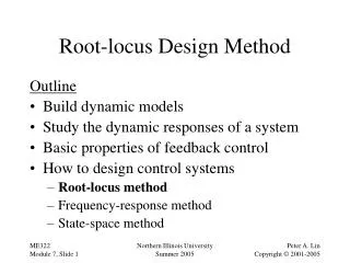
Main content • The Root Locus Concept • The Root Locus Procedure • Generalized root locus or Parameter RL • Parameter design by root locus method • PID controllers and RL method • Examples and simulation by MATLAB • Summary
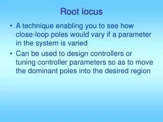
Introduction In the preceding chapters we discussed the relationship between the performance and the characteristic roots of feedback system. The root locus is a powerful tool for designing and analyzing feedback control system, it is a graphical method by determining the locus of roots in the s-plane as one system parameter is changed.
6.1 The root locus concept • Definition: The root locus is the path of the roots of the characteristic equation traced out in the s-plane as a system parameter is varied. • Root locus and system performance • Stability • Dynamic performance • Steady-state error
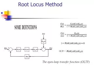
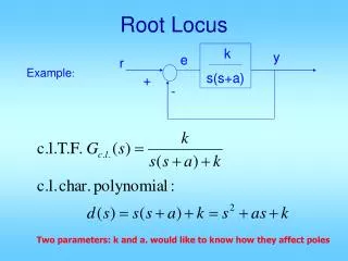
Root locus equation • Relationship between the open-loop and closed-loop poles and zeros • Root locus equation:
Basic task of root locus • How to determine the closed-loop poles from the known open-loop poles and zeros and gain by root locus equation. • Angle requirement for root locus • Magnitude requirement for root locus Necessary and sufficient condition for root locus plot Gain evaluation for specific point of root locus
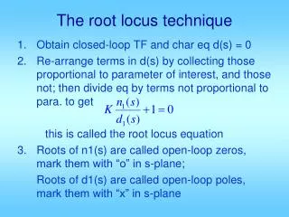
6.2 The Root Locus Procedure • Step 1:Write the characteristic equation as • Step 2: Rewrite preceding equation into the form of poles and zeros as follows:
6.2 Root locus procedure • Step 3: Locate the poles and zeros with specific symbols, the root locus begins at the open-loop poles and ends at the open-loop zeros as K increases from 0 to infinity. If open-loop system has n-m zeros at infinity, there will be n-m branches of the root locus approaching the n-m zeros at infinity.
6.2 Root locus procedure • Step 4: The root locus on the real axis lies in a section of the real axis to the left of an odd number of real poles and zeros. • Step 5: The number of separate loci is equal to the number of open-loop poles. • Step 6: The root loci must be continuous and symmetrical with respect to the horizontal real axis.
6.2 Root locus procedure • Step 7: The loci proceed to zeros at infinity along asymptotes centered at and with angles :
6.2 Root locus procedure • Step 8: The actual point at which the root locus crosses the imaginary axis is readily evaluated by using Routh criterion. • Step 9: Determine the breakaway pointd (usually on the real axis):
6.2 Root locus procedure • Step 10: Determine the angle of departure of locus from a pole and the angle of arrival of the locus at a zero by using phase angle criterion.
6.2 Root locus procedure • Step 11: Plot the root locus that satisfy the phase criterion. • Step 12: Determine the parameter value K1 at a specific root using the magnitude criterion.
An example • Fourth-order system • Refer to Table7.2 Illustration of complete procedure Page347-349 Summary of root locus procedure
Typical root locus diagrams • Refer to Table 7.7 (P381-383) An summary of 15 typical root locus diagrams is shown in Table 7.7
Assignment • E7.6 • E7.18