Laser Bar Code Scanner
Laser Bar Code Scanner. Chunyu Zhao. OPTI696D requirement. System overview: Describe the class of systems, stating the key metrics Explain the principles of how the system works Identify key subsystems, relate system performance to subsystem requirements.

Laser Bar Code Scanner
E N D
Presentation Transcript
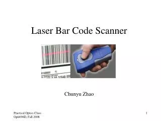
Laser Bar Code Scanner Chunyu Zhao
OPTI696D requirement • System overview: • Describe the class of systems, stating the key metrics • Explain the principles of how the system works • Identify key subsystems, relate system performance to subsystem requirements. • Summarize the current state of technology for this type of system • Analysis: • Disassemble the system and show key components and subsystems • Discuss features of this system and surmise design decisions
Outline • Barcode basics and laser scanners • How a laser scanner works • Scan engine: • Optical design and analysis • Manufacturing laser scanners in volume • State of the art scanning technology
Barcode basics:Type of barcodes • 1D barcode • UPC • Code 39 • Code 128 • etc • 2D barcode • PDF 417 • MaxiCode • etc
Barcode basics:Benefit of using barcodes • For retailers • Quickly identifying fast and slow selling items to help stocking decisions • Repositioning a given product within a store to move more profitable items to occupy the best space, • Historical data can be used to predict seasonal fluctuations very accurately. • For shipping companies • Keep track of packages from start to destination
1D laser scanners Handheld, single line Hand-free, multi-line Scan engine Fixed mount, multi-line
Key metrics • Size • Working range • Poor quality barcode reading capability • Width of field/scan angle • Pitch, roll and yaw angles • Barcode contrast • Ambient light level
How a laser scanner works • A laser spot is scanned across the bar code symbol that is to be read. • The light reflected from the symbol is directed to a photodiode where it is converted from optical energy to electrical current. • The signal is processed through both hardware and software, and the information it carries is extracted. Signal Processing: Hardware and Software
Scanning the Bar Code • When the laser is scanned across the bar code, the reflected signal is the convolution of the laser spot and bar code symbol. Simply stated, the convolution is the area of the overlap of the two waveforms. • In order to make finding the transition point from bar to space more easy to find, the signal is differentiated.
Sources of Noise • Internal Sources • Thermal noise of the electronic components. • Intrinsic noise of the preamplifier. • External Sources • Printed noise on the symbol. • Speckle noise created by the laser. • Sunlight. • Fluctuating ambient light. • EMI, RFI and power supply noise.
System performance defining factors • The characteristics that define how well a scanner will decode are • Depth of Modulation • laser focus • other optical components • Signal Amplitude • optical alignment • signal blockage • laser focus • optical AGC • Noise Amplitude • field of view • optical alignment • laser focus
Retro system: Scan mirror is part of the collection optics, so the FOV follows the laser spot. Small FOV, therefore less ambient light noise Small photodiode, so noise from PD is small. Need better alignment. Non-retro system: Scan mirror is NOT part of the collection optics, so the FOV is fixed and cover the whole scanning field, and it’s BIG. More ambient light noise. Need a big photodiode, thus the noise is huge, so the working range is reduced. Alignment is easier. Scanning Scanning Collection FOV Collection FOV Laser beam Laser beam Retro or non-retro system
The Design Process • To design a scanner you need to do the following things: • extract size and performance information from the customer or marketing spec • develop an optomechanical configuration • calculate optical field of view and photodiode size • develop a laser profile to meet the performance requirements • perform sensitivity study and tolerance analysis • develop inspection criteria for manufacturing
The most important part: laser beam profile • Laser Profile • Ideally, the cross section of the laser beam should be a Delta function. • In reality, the beam size is finite and expands as it propagates due to diffraction. • A small spot diameter is required to read high density bar codes. A large spot area is needed to minimize speckle noise and poorly printed symbols. Trade-off needs to be made.
The Laser Beam Profile: General Requirement • Basic requirement - the spot diameter must be no greater than some fixed multiple of the bar code symbol narrow element width over the entire working range. This multiple can range between 2.8 and 3.3 depending on the type and sensitivity of digitizer used. • Secondary requirement - ellipticity should be as large as possible to improve speckle noise characteristics and poorly printed symbol readability, and beam pedestal and ripple should be kept to a minimum.
The Laser Beam Profile • The characteristics of the laser beam can be controlled and manipulated using the following parameters; • position and focal length of laser focusing lens • aperture size, shape and aspect ratio • laser divergence angle and astigmatism • rotation of laser (high or low divergence in x axis) • external beam shaping optics
Scanning Optics • Flatness of mirrors controls accuracy of laser profile. • Curvature will shift waist size and location. • Random aberrations will distort overall beam shape. • Curvature can be used to add desired ellipticity, if applied to the Y axis.
A B Lens Barrel Tolerance analysis and error budget • Decenter: Lens Barrel vs. Laser • Decenter: Lens vs. Barrel • Decenter: Phase Plate vs. Barrel • Tilt: Lens Barrel vs. Laser
Collection Optics • Collect as much of the laser light reflected from the bar code as possible. • Track the position of the laser spot, and keep it in the center of the receiver field of view. • Define the size of the optical FOV to be as small as possible.
Optical Collection Area • A large collection area increases the signal received (improving signal to noise ratio) and reduces the effect of speckle noise, but makes the scanner physically bigger and collects more ambient light interference.
Optical Field of View • Alignment has to be maintained between what the laser illuminates and what the photodiode is looking at. A large FOV makes this alignment less critical, but increases the amount of ambient light collected and requires a larger photodiode to do the collecting, both degrading noise performance. A small FOV requires active alignment of the optics or higher tolerance parts, and it may move out of alignment with time or drop and vibration.
Optical filter • Right in front of the photo-detector • Let the laser reach the detector and block most of the ambient light
Manufacturing a scanner • Step 1: Focusing the laser module to obtain the desired beam profile • Step 2: Install collection and scanning optics, and detector • Step 3: Align the collection FOV with scanning beam Quality and yield!! Inspection DURING and AFTER production!!!
Optical alignment • Align the collection FOV with the flying laser spot: • For Non-retro system, adjust the center position of the flying spot to the axis of the collection optics • For Retro system, if the collection optics and scan optics are separated, then adjust the scan mirror to maximize the signal; otherwise alignment relies on tight mechanical tolerance
State of the art • Extended working range: • Double scan beams • Diffraction-free laser beam by using axicon