Performance Readiness
Wing to Fuselage Sub-Demonstrator TRL3 _ VISION OF IMPLEMENTATION. Performance Readiness.

Performance Readiness
E N D
Presentation Transcript
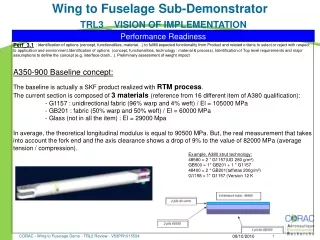
Wing to Fuselage Sub-DemonstratorTRL3 _ VISION OF IMPLEMENTATION Performance Readiness Perf_3.1: Identification of options (concept, functionalities, material…) to fullfill expected functionality from Product and related criteria to select or reject with respect to application and environment.Identification of options (concept, functionalities, technology : material & process). Identification of Top level requirements and major assumptions to define the concept (e.g. interface clash…). Preliminary assessment of weight impact A350-900 Baseline concept: The baseline is actually a SKF product realized with RTM process. The current section is composed of 3 materials (reference from 16 different item of A380 qualification): - G1157 : unidirectional fabric (96% warp and 4% weft) / El = 105000 MPa - GB201 : fabric (50% warp and 50% weft) / El = 60000 MPa - Glass (not in all the item) : El = 29000 Mpa In average, the theoretical longitudinal modulus is equal to 90500 MPa. But, the real measurement that takes into account the fork end and the axis clearance shows a drop of 9% to the value of 82000 MPa (average tension / compression). Example, A380 strut technology: 48580 = 2 * G1157(UD 280 g/m²) GB500 = 1* GB201 + 1 * G1157 48400 = 2 * GB201(taffetas 200g/m²) G1158 = 1* G1157 (Version 12 K CORAC - Wing to Fuselage Demo - TRL2 Review - V53PR1015504 08/10/2010
Wing to Fuselage Sub-DemonstratorTRL3_CWB Far Field Area : CFRP Strut & Fitting Performance Readiness Perf_3.1 : Initial evidence of concept (incl. new certification issues, if any) at component level with respects to environment and targeted application Present concepts versus analysis results (based on pre-sizing, or other preliminary studies…) LEADING TO DOWN SELECTION Identification of 3 solutions: As a partner in CORAC project, SKF proposes some improvements of its actual technology. The aim is to : - Decrease impact damage by using damping skin - Decrease buckling phenomena by using Unidirectional Braid (A350-900: braid ±45°) - Increase allowable stress by using polar patch. 1 2 3 1 3 2 2 removable half shells
Wing to Fuselage Sub-DemonstratorTRL3_CWB Far Field Area : CFRP Strut & Fitting Performance Readiness Perf_3.1 : Initial evidence of concept (incl. new certification issues, if any) at component level with respects to environment and targeted application Present concepts versus analysis results (based on pre-sizing, or other preliminary studies…) LEADING TO DOWN SELECTION Damping skin details: 1 Benefits: Protection of composite parts avoiding delamination Visualization of impacts => ease of maintenance Can be easily removed => ease of maintenance Position vs. Competition:New patented product for Airbus to protect composite parts against impact. • General concept of the Technology Product • External skin with high plastic deformation • Hollow spheres as energy absorber system External skin (aramid) Hollow spheres Composite Rod
Wing to Fuselage Sub-DemonstratorTRL3_CWB Far Field Area : CFRP Strut & Fitting Performance Readiness Perf_3.1 : Initial evidence of concept (incl. new certification issues, if any) at component level with respects to environment and targeted application Present concepts versus analysis results (based on pre-sizing, or other preliminary studies…) LEADING TO DOWN SELECTION Unidirectional braid details: 2 • UD braid is localized like the red line • Reduce thickness / radius of the lug • Reduce weight • increase allowable stress on fork end/ tube connection • decrease local buckling phenomena • Increase stiffness
Wing to Fuselage Sub-DemonstratorTRL3_CWB Far Field Area : CFRP Strut & Fitting • Reduce thickness / radius of the lug • Reduce weight • increase cleaving / bearing allowable stress • In line with specification • Increase stiffness Performance Readiness Perf_3.1 : Initial evidence of concept (incl. new certification issues, if any) at component level with respects to environment and targeted application Present concepts versus analysis results (based on pre-sizing, or other preliminary studies…) LEADING TO DOWN SELECTION Polar patch details: 3
Wing to Fuselage Sub-DemonstratorTRL3_CWB Far Field Area : CFRP Strut & Fitting Performance Readiness Perf_3.2 Compatibility/integrability Perf_3.2 Initial assessment of compatibility/integrability of component and cross technology issues (PDR) (incl. Systems installation and ramp-up requirements) Present product integration with respect to its environment highlighting major interface issue if any (tolerance, clash, corrosion, …) No interface modification: mettre photo du process/ ou schéma du cône 1 Aramid Plies Bonding (Hysol 9321) Clamping (x3) Mettre Photo après ébavurage 2 3
Wing to Fuselage Sub-DemonstratorTRL3 _ VISION OF IMPLEMENTATION • Impact tests on composite part protected by a damping skin (configuration c1) Clamping system Carbon plate Damping skin Carbon Plate C-San control : After 30 J impact, no internal delamination of composite parts after impact. After 50 J impact, defects appear (no visible). Definition of the baseline configuration c1 : AITM 1-0010 Standard 1.4 mm Aramid 5.8 mm hollow spheres Performance Readiness Perf_3.3 Initial technology trials addressing key features of component Present product technical test results addressing sizing/selection criteria 1 09 June 2008
Wing to Fuselage Sub-DemonstratorTRL3 _ VISION OF IMPLEMENTATION • Real Scale Manufacturing : • Impact on shells (in-shape damping skin) Al plate Higher Maximum effort Indentation Al Edge Displacement [mm] Performance Readiness Perf_3.3 Initial technology trials addressing key features of component Present product technical test results addressing sizing/selection criteria 1 Damping skin Rod 16000-08(real part) 09 June 2008
Wing to Fuselage Sub-DemonstratorTRL3 _ VISION OF IMPLEMENTATION Performance Readiness Perf_3.3 Initial technology trials addressing key features of component Present product technical test results addressing sizing/selection criteria 2 3 09 June 2008
Wing to Fuselage Sub-DemonstratorTRL3 _ VISION OF IMPLEMENTATION Performance Readiness Perf_3.3 Initial technology trials addressing key features of component Present product technical test results addressing sizing/selection criteria Test results analysis: 2 3 Cleaving section lug failure Rq: More flexibility on design capability to reach the combinaison of low stiffness and high load level F = ESε 09 June 2008
Wing to Fuselage Sub-DemonstratorTRL3 _ VISION OF IMPLEMENTATION Performance Readiness Perf_3.3 Initial technology trials addressing key features of component Present product technical test results addressing sizing/selection criteria 2 • Datas obtain on full scale rods permit us to: • Analyse failure load from test results → calculate rods failure load • Analyse σ cleaving and bearing of fork end → made optimized design with these values • Take stiffness results → defined stiffness in line with specification 3 *New design based only on tube modification 09 June 2008
Wing to Fuselage Sub-DemonstratorTRL3 _ VISION OF IMPLEMENTATION Performance Readiness Perf_3.4 Limitations for the technology Perf_3.4 Identification of basic design rules or limitations for the technology Rod stiffness: like serial spring (fork end/ cone/ tube) 1 2 3 • Keep same stiffness • Decrease tube thickness Decrease global ES (N) • Increase stiffness of : • Fork end by polar patch • Cone by using Unidirectional Braid instead of ± 45° • No other Limitations of the Technology • but increase of the damping layer weight and thickness with the absorption capacity needs (7.2 mm for 35 J and 13.4 mm for 50 J)
Wing to Fuselage Sub-DemonstratorTRL3 _ VISION OF IMPLEMENTATION • See Perf. 3.1 • C-san control for 3 tested composites plates (Résultats St Vallier !!!!) Ok for 30 J Ok for 50 J Performance Readiness Perf_3.5 Material characterisation Perf_3.5 Initial evidence of material characterisation through coupon testing on reference loads to prove key characteristics (TRL4 for dimensioning new material) Present material candidates screening results in the format of a spider diagram to compare with standard material. 1 09 June 2008
Wing to Fuselage Sub-DemonstratorTRL3 _ VISION OF IMPLEMENTATION Performance Readiness Perf_3.6 Scale-up issues Perf_3.6 Scale-up issues addressed through design of scaled components to include specific features targeted in the demonstration Present scale-up issue mitigation plan progress and demonstrate risk management & reduction. 1 Flat specimens 150 x 150 mm² Cylindrical specimens (F 89 mm - Real part) Non - Flat specimens ( l = 180 mm) First tests on flat damping layers have been successfully extrapolated to landing gear rods. Same approach is used for the composite rods (A350 Application). 09 June 2008
Wing to Fuselage Sub-DemonstratorTRL3_CWB Far Field Area : CFRP Strut & Fitting Engineering Readiness • Eng_3.1 Confirmation of a sponsor acceptance • For the A350-1000 and potential retrofit on other Airbus program • Eng_3.2 Appropriate multidisciplinary team • Eng_3.2 Identification of appropriate multidisciplinary team to review and/or develop the new technology (i.e. M&P, EDS, CoC...) • Airbus Team, NDT expert for non destructive test, SKF for manufacturing and design, Ateca for the damping skin • Eng_3.3 Material preliminary specification • Eng_3.3 Identification or production of an appropriate material preliminary specification • UD Braid: same fiber than already qualified tube material • Polar patch: AS4 fiber for Hexcel (standard list materials) 1 2 3 1 2 3 2 3 Wing box rods specification n° V00030001 curent version
Wing to Fuselage Sub-DemonstratorTRL3_CWB Far Field Area : CFRP Strut & Fitting Engineering Readiness • Eng_3.3 Material preliminary specification • Eng_3.3 Identification or production of an appropriate material preliminary specification • Damping skin materials: 1 • Aramid Fabric K336 (Sicomin) • Epoxy Resin Araldite LY5052/ Aradur 5052 (Airbus database) • FAR 25 certified hollow spheres (ATECA), used by EADS Eurocopter since 2002 ( for vibroacoustic application) • Adekit 211 (Axson) • Work in progress : • Environmental condition tests (fuel, wet ageing). PHOTOS ST vallier!!! • Research of new Airbus certified adhesives
Wing to Fuselage Sub-DemonstratorTRL3_CWB Far Field Area : CFRP Strut & Fitting Engineering Readiness Eng_3.4 Validation of pre-sizing methods Eng_3.4 Validation of pre-sizing methods with respects to lessons-learnt from material and manufacturing screening 1 • Low energy Impact Tests performed by Conseil & Technique on week 15 … • See Perf. 3.3 and :
Wing to Fuselage Sub-DemonstratorTRL3_CWB Far Field Area : CFRP Strut & Fitting Engineering Readiness • Eng_3.4 Validation of pre-sizing methods • Eng_3.4 Validation of pre-sizing methods with respects to lessons-learnt from material and manufacturing screening • Present pre-sizing methods used and show its reliability with respects to lessons-learnt from material, manufacturing screening, etc… • SKF High knowledge for rods design • Using first results from sample for lug section • Using damping skin result for tubular section design • Test on complete rod will be done on week 15 to validate first design 2 3 Datas establish from sample
Wing to Fuselage Sub-DemonstratorTRL3_CWB Far Field Area : CFRP Strut & Fitting Engineering Readiness Eng_3.5 Preliminary Certification Plan Eng_3.5 Preliminary Certification Plan incl. Showstoppers • Witch A350-900 rod reference must be tested? • A Jonhson/Euler or mixte failure mode reference • High fork end thickness due to high cleaving/bearing stress
Wing to Fuselage Sub-DemonstratorTRL3_CWB Far Field Area : CFRP Strut & Fitting TRL 3 damping skin TRL 6 TRL 5 TRL 4 TRL 3 Engineering Readiness Eng_3.5 Preliminary Certification Plan Eng_3.5 Preliminary Certification Plan incl. Showstoppers Damping skin: 1
Wing to Fuselage Sub-DemonstratorTRL3_CWB Far Field Area : CFRP Strut & Fitting TRL 3 UD braid/ polar patch TRL 6 TRL 5 TRL 4 TRL 3 Engineering Readiness Eng_3.5 Preliminary Certification Plan Eng_3.5 Preliminary Certification Plan incl. Showstoppers Polar patch and UD braid: 2 3
Wing to Fuselage Sub-DemonstratorTRL3_CWB Far Field Area : CFRP Strut & Fitting Engineering Readiness Eng_3.6 Compatibility with environmental and H&S legislation Eng_3.6 Initial assessment of compatibility (benefit/risk) of material, manufacturing process… with environmental and H&S legislation, identification of mitigation opportunities For this assessment, you can ask for a dedicated Enviromental Life Cycle Analysis (ELCA) 1 2 3
Wing to Fuselage Sub-DemonstratorTRL3_CWB Far Field Area : CFRP Strut & Fitting Manufacturing Readiness Manuf_3.1 Manufacturing trials to produce small-scale shaped test components Manuf_3.1 Initial assessment through manufacturing trials to produce small-scale shaped test components with respects to key characteristics See Perf_3.3for ud braid and polar patch. 2 3 ±45° braid UD braid • Damping layers successfully manufactured to protect real scale rods for aircraft landing gear. • Manufacturing of demonstrator subparts in March 2011 (Protection of rod 16000-08). 1 89 mm
Wing to Fuselage Sub-DemonstratorTRL3_CWB Far Field Area : CFRP Strut & Fitting Manufacturing Readiness • Manuf_3.2 Potential manufacturing hot spots • Manuf_3.2 Identification of potential manufacturing hot spots and high risk areas with respect to robust manufacturing and (inner) quality, manufacturing defects and related inspection methods • No risk for UD braid, exactly the same process than standard A350-900. • For polar patch, the positionning must be in line with drilling localization • For damping skin : • Porosity of the aramid skin has to be controlled. • Standard NDT Inspection not applicable • New procedures should be defined to check the damping layers after manufacturing (In Progress with NDT Expert). 2 possibilities: • shearography os US inspection • or • Y To increase the trust in the manufacturing process – use of aramid prepreg (In Progress). 2 3 1
Wing to Fuselage Sub-DemonstratorTRL3_CWB Far Field Area : CFRP Strut & Fitting Manufacturing Hollow spheres manufacturing Same process as for EADS-Eurocopter Hollow spheres assembly (bonding) Curing NDT Hollow spheres bonded on to the external skin -Machining- External Skin cutting (laser , same procedures than SAFRAN) Damping layer clamped to the rod Manufacturing Readiness Manuf_3.3 Suitable model for the manufacturing method and component performance Manuf_3.3 Development of a suitable model for the manufacturing method and the component performance Present the serial manufacturing process that complies with product performance 1 Manufacturing vacuum bag Processing for eternal skin
Wing to Fuselage Sub-DemonstratorTRL3_CWB Far Field Area : CFRP Strut & Fitting Manufacturing Readiness • Manuf_3.4 Manufacturing process repeatability • Manuf_3.4 Preliminary assessment of manufacturing process repeatability • For Ud braid and polar patch: same process than standard rods, with robust concept. For damping skin, Industrial Process at small scale: • Hollow spheres manufacturing already exists to answer to small scale industrial needs (EADS- Eurocopter) • but some discrepancies appeared in the external skin porosity. • YThis would be improved using aramid Prepreg (In Progress). • Manuf_3.5 Tolerance management philosophy for component & manufacturing tooling • Manuf_3.5 Assessment of tolerance management philosophy for the component and manufacturing tooling • Similar tooling than existing qualified part. • Manuf_3.6 Concepts for new tooling • Manuf_3.6 Identification of concepts for new tooling capabilities (TRL1 for new tooling capabilities) to go to next levels of demonstration (incl. Plan for demonstrator if required) • The prototype tooling is the same concept than serial tooling. Only material (Aluminium versus Steel) is different. • Manuf_3.7 Assembly issues • Manuf_3.7 Identification of assembly issues (i.e. bonding drilling, fastening methods etc…) and mitigation plan defined • No issue concerning this point : damping layers clamped on the struts.
Wing to Fuselage Sub-DemonstratorTRL3_CWB Far Field Area : CFRP Strut & Fitting 15 J 30 J Operational Readiness Op_3.1 Repair solution for both manufacturing defect and in-service requirements Op_3.1 Preliminary assessment of repair solution for both manufacturing defect and in-service requirements No repair on this CFRP part. Part replacement necessary. Feed back from Airbus EIOI assessment showing no issues in the past years Op_3.2 Impact on support services Op_3.2 Assessment of impact on support services (acceptability by A/L ie maintenance processes, tools, skills, DOC/DMC…) 1 2 3 • During maintenance process, damping layers should be controlled. • Inspection needed to check the rod integrity after impact • Criteria to change the damping layer : indentation value (in progress) 1 20 mm Indentations on a damping layer after 15 J and 30 J impact
Wing to Fuselage Sub-DemonstratorTRL3_CWB Far Field Area : CFRP Strut & Fitting Value & Risk V&R_3.1 & 3.2 Benefits and risk analysis V&R_3.1 Update of benefits and risk analysis with respects to environment of application and feasibility results (material, component, scale-up and production constraints, preliminary manufacturing time cycle analysis, new certification issues if any…). Present weight & cost analysis and exchange rate. 1 2 3 • Hypothesis: • Move from visibility criteria to cut off (35J) • Stiffness calculation based on 008 rods test results • Damping sking protection of 50g/dm² maximum to get weight saving • Fork end thickness based on 008 rods test results
Wing to Fuselage Sub-DemonstratorTRL3_CWB Far Field Area : CFRP Strut & Fitting Value & Risk V&R_3.1 & 3.2 Benefits and risk analysis V&R_3.1 Update of benefits and risk analysis with respects to environment of application and feasibility results (material, component, scale-up and production constraints, preliminary manufacturing time cycle analysis, new certification issues if any…). Present weight & cost analysis and exchange rate.
Wing to Fuselage Sub-DemonstratorTRL3_CWB Far Field Area : CFRP Strut & Fitting Value & Risk Route to TRL4 • Confirm sample result on full scale rods • Redesign and optimized the part with the TRL3 test result • Potential other failure modes identification (braid lenght, polar patch number) • Test, @ temperature and fatigue/ageed condition • Damage and defect tolerance tests and associated destructive and Non Destructive Test reports • Variability assessement • Test with A350 baseline rods for global stiffness measurement on dedicated test bench TRL3 TRL4
Wing to Fuselage Sub-DemonstratorTRL3_CWB Far Field Area : CFRP Strut & Fitting Route to TRL6 • Damping skin industrialization parameter to be fixed • Confirm sample result on complete rods • UD braid • Polar patch • Damping skin • Obtain optimized design based on test realized on full scale rods • adjust the stiffness in line with specification • Manufacturing rods parameters to be fixed • Obtain polar patch localization effect • Obtain optimized damping skin length protection and material fixed • Obtain allowble material necessary for design part • NDT parameters to be fixed TRL5 TRL6 TRL3 TRL4 Value & Risk