Download
1 / 13
130 likes | 154 Vues
A detailed analysis of flow dynamics beyond the stage in a multi-stage turbine, focusing on radial equilibrium theory and its implementation for stable operation. Understanding the importance of flow through stator, rotor, and inter-stage gaps.

E N D
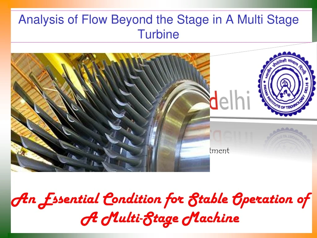
Analysis of Flow Beyond the Stage in A Multi Stage Turbine P M V Subbarao Professor Mechanical Engineering Department An Essential Condition for Stable Operation of A Multi-Stage Machine
Geometrical Details along the Third Direction • Flow and tangential (Whirl) velocities are very important for operation of a turbo-machine. • True flow through a turbo-machinery is three-dimensional. • The third component, which is normal to flow and tangential directions is of no use. • This direction can better identified as blade height direction.
Third Direction of an Axial Flow Turbo-Machines • The third direction in an axial flow machine is the radial direction. • The direction of Centrifugal forces! • Strong centrifugal forces are exerted on blades & fluid in radial direction. • The centrifugal force field distorts the flow velocity profiles considerably. • Fluid particles tend to move outwards rather than passing along cylindrical stream surfaces as classically assumed. • Particularly in tall blade (low hub: tip) ratio designs. • An approach known as the radial equilibrium method, widely used for three-dimensional design calculations in a an axial flow machine.
Radial Equilibrium Theory • Assumes that flow is in radial equilibrium before and after a rotor blade row. • Radial adjustment takes place through the moving blade passage. • More important for Axial Flow Machines.
Radial Equilibrium Analysis The centrifugal force = (rrdrdq)w2r Vw= rw The centrifugal force is The pressure force on the element
If the two forces are the only ones acting (viscous and other effects neglected), the particle will move at constant radius if:
Equilibrium Condition for A Rotating Fluid A mechanical equilibrium of a fluid elements demands thermodynamic equilibrium. The fluid must be facilitated to adjust radially as per the requirements. This process of radial adjustment of fluid parcels is well assumed to be isentropic. The radial variation of whirl velocity should be according to above equation. How to implement on a machine?
Implementation of Radial Equilibrium Stagnation enthalpy should conserve along radial direction, as there are not interactions with rotor at inlet or exit of rotor.
Radial component of velocity should be constant (zero) along radial direction for radial equilibrium of flow.
Constant in a turbo-machine along meridoinal Plane Stagnation enthalpy is Constant in a turbo-machine along radial direction at intake and discharge.