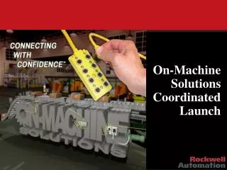
On-Machine Solutions Coordinated Launch
360 likes | 532 Vues
On-Machine Solutions Coordinated Launch. What is Distributed Architecture?. Distributed. Traditional. Advantages of On-Machine Architecture Reduced Wiring Simplified Connectivity Minimized Space Requirements Reduced Commission Time Reduced Design Time Enhanced Diagnostics.

On-Machine Solutions Coordinated Launch
E N D
Presentation Transcript
What is Distributed Architecture? Distributed Traditional • Advantages of On-Machine Architecture • Reduced Wiring • Simplified Connectivity • Minimized Space Requirements • Reduced Commission Time • Reduced Design Time • Enhanced Diagnostics • Disadvantages of Traditional Centralized Panel Architecture • Complex Wiring • Difficult to Troubleshoot • Increased Engineering Time • Large Panel Space Requirements
Simply put, we are putting components and control on the machine “In-Cabinet” “On-Machine”
Economics 101 DESINA estimate is 17% total cost reduction for OEM
Economics 102 Although the cost of individual components used in On-Machine solutions can be more than those used in In-Cabinet applications, the savings in assembly cost make the overall cost of the machine less. In large machines you can save in both assembly and material cost. This is due to material saving in wire and cabinets.
ArmorStart Bul. 280/281 Ratings • Motor Horsepower Range .5- 10 HP (.37-7.5 kW) • 200-480 VAC line voltage • Control power ratings 24VDC, 120VAC or 240VAC • 50/60 Hz • 0-40° C Operating Temperature • Approval Ratings: cULus and CE
Bulletin 280/281 ArmorStart Product Overview • Full Voltage and Reversing Applications • Built in adjustable overload • Class selectable 10,15 or 20 selectable • Manual or Automatic overload reset • Increased controller diagnostics • Visible LED’s for controller status and I/O indication • Robust Modular IP67 design • Motor cable provided as standard • 3 meter unshielded 4 conductor singled ended cordset • Supports ADR(auto device replace)for rapid re-commissioning • Ability to upgrade controller without rewiring base or I/O
ArmorStart Design LED Status Indication Local CB Disconnect Accepts 3 padlocks Provides for group motor protection 4 Inputs: (Micro/M12) 2 Outputs: (Micro/M12) DeviceNet (Mini/M18) Motor connection cable
ArmorStart with Motor and I/O Connections 4 Inputs: (Micro/M12) 2 Outputs: (Micro/M12) DeviceNet (Mini/M18) Cover Plate for Incoming power and control wiring Motor connection cable
Incoming Power and Control Voltage Connections Incoming Power and Control voltage connections Dual connections for ease of daisy chaining
Modular Design Removable Control Module Control Module can be removed without unwiring base
Mounting Dimensions Depth is 140 MM or 5.5”
ArmorStart Optional Keypads • Optional Factory Installed HOA Keypads
Built in LED Status Indication • Power LED - Indicates power is present • RUN LED - When motor is running • Network LED - Indicates status of communication link • Fault LED - Indicates Controller Fault (trip) condition • Reset Button - as local trip reset
Bulletin 280/281 Fault Diagnostics • The built in fault diagnostics allows the easy troubleshooting of the ArmorStart • Circuit Breaker Trip • Overload • Phase Loss • Control Power Loss • Phase Imbalance • Sensor Input Short Circuit • DeviceNet Power Loss
ArmorStart Set-up and Monitoring • Built in adjustable overload-programmed via DeviceNet • Overload class is selectable • Manual or automatic overload reset • Percent motor thermal capacity used • Overload reset point/value • Motor currents may be monitored
Labor Cost Savings • Traditional motor wiring costs* • If a combination starter without any quick disconnect means was 6 feet from the motor, here is an estimate of the cost to wire the motor: *Cost estimated based on commercially available contractor estimating tools
Labor Cost Savings • Labor Cost Savings with ArmorStart Distributed Motor Controller • A 3 meter unshielded 4 conductor singled ended cordset is provided as standard with every ArmorStart Distributed Motor Controller Total motor wiring cost is $51.00 per full voltage starter. $136 (Traditional Wiring) – $ 51 (ArmorStart Distributed Motor Controller) = $ 85 in savings per motor connection
Bulletin 284 Product Ratings • Variable Frequency AC Drive using PowerFlexTM Technology • Voltage Ratings • 240 V AC, 50/60 Hz, Three Phase • 480 V AC, 50/60 Hz, Three Phase • Horsepower Ratings • 0.5-2.0 @ 240 V AC • 0.5-5.0 @ 480 V AC • Motor cable provided as standard • 3 meter unshielded 4 conductor singled ended cordset • Robust IP 67/Nema Type 4 enclosure rating • 0-40° C Operating Temperature • Approval Ratings: cULus and CE
ArmorStart Variable Frequency-Standard Features • Overload Current • 150% for one minute • 200% for 3 seconds • Digital response time • 10mSec for stop • 22mSec for starting with 2mSec repeatability • 2 wire high speed mode improves response to 10mSec • Targeted for high speed packaging and simple positioning applications • Two output current sensors • ensures excellent current accuracy • One ground fault sensor • ensures protection against ground faults during start and run conditions
Fault Diagnostics Short Circuit Overload Phase Short Ground Fault Stall Control Power Loss Input Short Circuit DeviceNet Power Loss Internal Communication Fault DC Bus Fault Over temperature Over Current
1738 ArmorPoint I/O • Scalable IP67 Architecture Built on Point I/O Technology • Programmed and mapped the same as Point I/O • Reuse of Logix and RSNetworx knowledge • No software training Desktop PC
DeviceNet Adapters • Common to all: • 4 pin Auxiliary Power for inputs, outputs, and backplane • Two rotary address switches under M8 sized caps • Network and Power Status LEDs • Terminating base shipped with adapter • 1738-ADNX • Male Dnet In M12 • Female Subnet Out M12 • Drop from trunk, Subnet • 1738-ADN12 • Male Dnet In M12 • Female Dnet Out M12 • Drop or pass-thru • 1738-ADN18 • Male Dnet In Mini • Drop only • 1738-ADN18P • Male Dnet In Mini • Female Dnet Out Mini • Drop or pass-thru • Terminating Base • One shipped with every Adapter • Replaces regular mounting base • Terminates the Point Sub-bus.
EtherNet, ControlNet, and Profibus EtherNet I/P In Adapter Status x100 Network Activity Network Status PointBus Status x10 System Power Adapter Power x1 PWR • Common to all: • 4 or 5(Profibus) pin Auxiliary Power for inputs, outputs, and backplane • 2 or 3(EtherNet I/P) rotary address switches under M8 sized caps • Network and Power Status LEDs • Terminating I/O base shipped with adapter • 1738-APB • Reverse key • Male Pbus In M12 • Female Pbus Out M12 • Drop or pass-thru • 5-pin Aux Power • 1738-ACNR • Redundant TNC connectors • Bul. 1786 • 4-pin Aux Power • 1738-AENT • Male Enet In 4-pin M12 • Special D-Key • 4-pin Aux Power
ADNX Architecture DeviceNet Trunk • Consolidate nodes • Double the distance! Sub-bus Node 1 Sub-bus Node 2 DeviceNet Subnet Sub-bus Node 5 Sub-bus Node 6 Sub-bus Node 3 Sub-bus Node 4
Low-cost IP67 I/O 1732 ArmorBlock™ I/O
1732 ArmorBlock Front Mounting Holes Product Offerings DeviceNet or Profibus DeviceNet 1732D-IB8M12 1732D-IB8M8 1732D-OB8EM12 1732D-OB8EM8 1732D-8CFGM12 1732D-8CFGM8 Profibus 1732P-IB8M12 1732P-IB8M8 1732P-OB8EM12 1732P-OB8EM8 1732P-8CFGM12 1732P-8CFGM8 8 Inputs Address switches under caps 8 Outputs 8 Self-Configuring 4-M12 (DC Micro) or 8-M8 (Pico) I/O connectors Product Features • 24V dc • Quick-Connect option for DeviceNet • Outputs Short Circuit Protected • Output monitoring in Self-Configuring style Status LEDs Sensor and Actuator Power Side Mounting Holes (Not for use with Profibus)
Not an All-or-Nothing Proposition Distributed Enclosures Distributed Power DIO EOI DSS DIO DIO IP20 Device Box New KwikLinkTM & Flexible Flat Media DeviceNetTM Round Media Connectorized Safety Wiring System Main Control Cabinet IDC Field Attachables PanelConnectTM Safety Device Cordsets & Patchcords E3 Drive PLC Safety Device Safety Device Safety Device Passive Distribution Box Safety Relay Safety Device New KwikLink & Flexible Flat Media Distributed Control Centralized Control IP20 IP6x
Connection Systems – Panel ConnectTM for Sensors • Development from Wiring Systems group in Milwaukee • Direct plug and play for sensors direct to the PLC • AB connectivity from PLC to sensor with 889 and 898 products • Specific models available for use with inputs or outputs • Supports use with 8-port distribution boxes • OEM focused product • Shipping Today!
Rockwell’s Growing On-Machine Product Suite Connection Systems / DNet Media Distributed IP67 I/O Sensors, Actuators and Enunciators IP67 Distributed Motor Controller
AB Connection Systems Field Attachable Connectors Patchcords Cordsets Passive Distribution Boxes Panel Mount Receptacles Y-cables & Splitters Pico (M8) DC Micro (M12) AC Micro (dual key) Mini Mini-Plus M23
New Products! IDC Field Attachable Connectors • Features • Insulation Displacement Connector technology (IDC) • 3- and 4-pin, DC Micro and Pico • Male and female, straight and right angle • Quick and easy field installation with virtually no tools • Benefits • Allows fast & simple custom cable lengths on the fly • Up to 50% faster installation than screw type • Installation in 4 easy steps as shown below: In Stock Now! 1.Stripouter cable jacket to between 15mm – 20mm (0.6” – 0.8”). 2.Assemble connector components (rear housing, cable grommet, and plastic insulator) onto stripped cable as shown, matching conductors to numbered color-coded holes. 3.Trimconductors flush with front of plastic insulator after ensuring cable jacket is fully seated against rear of plastic insulator. 4.Twist together rear housing and main connector housing then firmly hand-tighten.
Why Should You Be Interested? Re-Configurability • No need to redesign the panel, run new pipe and re-terminate wires that have already been run. Simply add the desired component and go. What Customers Say: David Girard at Cinetic Automation says, “If the customer wants to add a device to an auto station, they don’t need to question whether or not they have enough panel space because there’s no panel space required.
Why Should You Be Interested? Reliability • On-Machine solutions can minimize wiring errors because wiring is pre-manufactured with quick-disconnect features. With less wiring involved, there are fewer points of failure. What Customers Say: Nick Mercorella, plant engineer at Continental P.E.T. Technologies Inc., says, “We were able to install our entire system without ever screwing a wire down, thus eliminating any potential miswiring and the system debugging cost associated with such problems. It’s true plug-and-play, which is exactly what we needed.”
Why Should You Be Interested? Reduced Floor Space • Industries like semiconductor and pharmaceutical manufacturing have realized the benefits of the On-Machine approach for years, as their clean-room space is at a premium. What Customers Say: Cinetic Automation customers average 70 auto stations in their assembly lines, each one taking about 20 square feet. With enclosures taking up an average of 10 to 12 feet of space at each station, their elimination results in some drastic plant floor space savings.