Instrumental Analysis
350 likes | 617 Vues
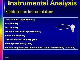
Instrumental Analysis. Electrical Components and Circuits. Laws of Electricity. Component Symbols. Power sources (V) and common connections (GND). Relay. Manual switch. Optocopler. Optocoupler. Optocoupler. Resistors. Electrical Components. Electronic Components Resistors.

Instrumental Analysis
E N D
Presentation Transcript
Instrumental Analysis Electrical Components and Circuits
Component Symbols Power sources (V) and common connections (GND)
Relay Manual switch Optocopler
Resistors Electrical Components
Electronic Components Resistors Resistor Color Rings A Resistor Value is determined by its color band and is measured in ohms First Ring is units Second Ring is Ten Third Ring is number of zero’s Fourth Ring is tolerance Resistor Color Code Values First Ring Black = 0 Brown = 1 Red = 2 Orange = 3 Yellow = 4 Green = 5 Blue = 6 Violet = 7 Gray = 8 White = 9 Second Ring Black = 0 Brown = 1 Red = 2 Orange = 3 Yellow = 4 Green = 5 Blue = 6 Violet = 7 Gray = 8 White = 9 Third Ring Multiplier Silver = X .01 Gold = X .1 Black = X 1 Brown = X 10 Red = 2 = X 100 Orange = 3 = X 1000 Yellow = 4 = X 10,000 Green = 5 = X 100,000 Blue = 6 = X 1000,000 Violet = 7 = X 10,000,000 1m 12m Pg 7
Direct CurrentSeries Circuit I Ohm’s Law Kirchhoff’s Laws
Photoresistors Variable resistors Thermistor
Electrolyte Nonelectrolyte Capacitors
Transformers Variac
Component Symbols Inductors (L) and Transformers (T) simple inductors adjustable adjustable tapped The two parallel lines indicate that the inductor is wound on a core of iron, iron powder, or ferrite material. transformers
H.V transformer Tesla Coil TV-Line Car Ignition
Symbols Electronic Components Microphone Outputs voltage Batteries In volts Inductor or Coil In henries Resistor In Ohms + Power Supply Outputs Volts Transformer Input voltage Speaker Input voltage Potentiometer Variable Resistor 120V AC In DC volts Out Isolated Capacitors In Farads Step Down + Step Up 2m 2m Pg 3
Measuring Devices Multimeters: Analogue
Time domain measuring instruments Oscilloscope
Signal / Coaxial Cables & BNC connectors RS232 / 9-pin GPIB /IEEE Cable RS232 / 25-pin