Comprehensive Guide to Instrumental Analysis Techniques
520 likes | 665 Vues
Learn about sampling, data handling, and calculation in analytical chemistry. Explore spectroscopy, chromatography, and electro analytical chemistry. Discover instruments used in the lab, such as AA Spectrophotometer and Gas Chromatograph. Understand the basic principles and components of Atomic Absorption Spectroscopy.

Comprehensive Guide to Instrumental Analysis Techniques
E N D
Presentation Transcript
TOPIC INSTRUMENTAL ANALYSIS PRESENTER NAZIR AHMED FARAZ Apprentice Chemist
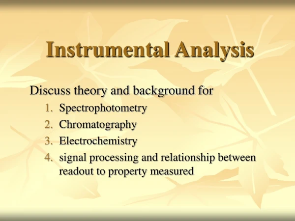
ANALYTICAL STRATEGY FOR ANALYSIS Following are the main steps involved in an analysis. Sampling Sample preparation Analytical method Data handling Calculation & Reporting of results
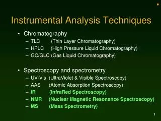
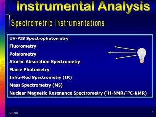
CATAGORIES OF INSTRUMENTAL ANALYSIS Spectroscopy: Involved in using some light and measure the amount of either absorbed or emitted light by solutions of analyte under certain conditions. e.g. Atomic Absorption Spectrophotometery, UV/Visible spectroscopy, etc . Chromatography: Involves more complex samples in which analyte is separated from interfering substances using specific instruments. Components are electronically detected with the electrical signal generated by detection devices. e.g. Gas Chromatograph. Electro Analytical Chemistry: Involves measurement of voltage or current resulting from electrodes immersed into solution. e.g. pH Meter.
COMPONENTS OF INSTRUMENTS Sensor: It is a type of translator that converts some property (T, P, Light or pH) of analyte into weak electrical signal. Signal Processor: It amplifies or scales the signal and converts it to a useable form. Readout Device: It displays the signal for analyst to see components. Power Supply; It provides the power to run these components. Standard & Sample Solutions Signal Processor Readout Devices Sensor Power Supply
VARIOUS ANALYSES CARRIED OUT IN FFBL LABORATORY • Water Analysis • Product Analysis • Raw Material Analysis • Metal Analysis • Gas Analysis, etc
INSTRUMENTS USED IN FFBL LABORATORY • Atomic Absorption Spectrophotometer • Gas Chromatograph • UV - Visible Spectrophotometer • Karl Fisher Titrator • pH Meter • Conductivity Meter, etc.
AA Spectrophotometer Atomic Absorption Spectroscopy Atomic absorption spectrophotometer being used in FFBL laboratory
BASIC PRINCIPLE: • ATOMIC ABSORPTION SPECTROSCOPY (AAS) is an analytical technique that measures the concentrations of atoms. It makes use of the absorption of light • by these atoms in order to measure their concentration. • - Atomic-absorption spectroscopy quantifies absorption of ground state atoms in the gaseous state. • The Atomic Absorption: • Atomic absorption spectrometers have 4 principal components: • 1 - An atom cell ( atomizer ) • 2 - A light source ( usually a hollow cathode lamp ) • 3 - A monochromator • 4 - A detector , and read out device.
Schematic Diagram of an Atomic Absorption Spectrometer Light source atomizer monochromator Detector and hollow cathode Lamp readout device 1 – Atomizer: Elements to be analyzed needs to be in atomic sate. Atomization is separation of particles into individual molecules and breaking molecules into atoms .This is done by exposing the analyte to high temperatures in a flame or graphite furnace .
Flame Flame AA can only analyze solutions , where, it uses a slot type burner to increase the path length, and therefore to increase the total absorbance . Sample solutions are usually introduced into a nebulizer being sucked up by a capillary tube. In the nebulizer the sample is dispersed into tiny droplets, which can be readily broken down in the flame. Excited State Atoms Light Emission Source Excitation + De-excitation (Resonance) Absorption Measured Free Ground State Atoms Light Source Atomization Ionic Formula Units Solvent Evaporation
2- Light Source The light source is usually a hollow cathode lamp of the element that is being measured. It contains a tungsten anode and a hollow cylindrical cathode made of the element to be determined. e- M Hollow Cathode Lamp: Ar + Ar+ Ar + + + + - - - - M+ Light M M M+ Ar +
3- Monochromator: Entrance Slit Dispersing Element Source Spray of Rainbow Colors Violet 4- Detector and Read out Device: Monochromatic Green Light To Source Exit Slit The light selected by the monochromator is directed on to a detector that is typically a photomultiplier tube , whose function is to convert the light signal into an electrical signal convert proportional to the light intensity. Red
Analysis of Iron (Fe) 1.00 mL pipette 1 mL 2 mL 3 mL 4 mL 5 mL Fe: 0.05 mg mL-1 50.00 mL volumetric flasks
Determination of Fe Absorbance
Gas Chromatograph (GC) The separation of a mixture by distribution of its components between a mobile and stationary phase over time. Gas Chromatograph being used in FFBL Laboratory
Gas Chromatography Gas - liquid Gas - solid Purpose of Chromatography: Analytical - determine chemical composition of a sample. Preparative - purify and collect one or more components of a sample. Classification
Gas Solid Chromatography: This method is based upon adsorption of gaseous substances on solid surfaces. • Distribution coefficients are generally much larger than those for gas-liquid chromatography • Used primarily for the separation of species that are not retained by gas-liquid columns such as the components of air, hydrogen sulfide, carbon disulfide, NOx, CO, CO2, and the rare gases.
H RESET Air Hydrogen Gas Carrier Gas Chromatography • Gas inlet system • Column • Detector • Data system
Detectors for GC • Flame ionization (FID) • Destruction of combustible sample in flame produces measurable current. • Thermal conductivity (TCD) • Change in resistance of heated wire. Flame Ionization Detector: High temperature of hydrogen flame (H2 +O2 + N2) ionizes compounds eluted from column into flame. The ions collected on collector or electrode and recorded on recorder due to electric current.
Thermal Conductivity Detector Measures the changes of thermal conductivity due to the sample (mg). Sample can be recovered without destruction. Principal: Thermal balance of a heated filament When the carrier gas is contaminated by sample , the cooling effect of the gas changes. The difference in cooling is used to generate the detector signal. The TCD is a nondestructive, concentration sensing detector. A heated filament is cooled by the flow of carrier gas. Flow Flow
UV Spectrophotometer Spectral Distribution of Radiant Energy Wave Number (cycles/cm) X-Ray UV Microwave Visible IR 200nm 400nm 800nm WAVELENGTH(nm)
Principle of UV/VIS Spectrophotometer: • Light Intensity Change : By Absorbance or Transmittance • Quantity : Using Absorbance The human eye sees the complementary color to that which is absorbed
Lambert-Beer’s Law: Light I0 I A = abC a = Absorbance Constant b = Sample path length C = Sample Concentration Cell filled with solution Absorbance Standard Curve, Calibration curve: • Standard Samples • Proportional Constant • Absorbance Measurement of Samples Concentration
Limitation of Lambert-Beer’s Law: • At high concentrations (>0.01M) due to electrostatic interactions between molecules in close proximity. • Scattering of light • due to particulates in the sample • Fluorescence or Phosphorescence of the sample • Changes in refractive index at high analysis concentration • Shifts in chemical equilibria as a function of concentration • Stray light
LIGHT SOURCES UV Spectrophotometer Deuterium Lamp Visible Spectrophotometer Tungsten Lamp Wavelength Range: 190 ~ 420nm Wavelength Range: Part of UV and Whole of Visible Range
Absorption Cells UV Spectrophotometer Quartz (crystalline silica) Visible Spectrophotometer Glass
Karl Fisher Titration The fundamental principle behind it is based on the Bunsen Reaction between iodine and sulfur dioxide in an aqueous medium. Karl Fisher Titrator being used in FFBL Laboratory
Karl Fischer Reaction: • ROH + SO2 + R’N [R’NH]SO3R + H2O + I2 + 2R’N 2[R’NH]I + [R’NH]SO4R • [alcohol] [base] [alkylsulfite salt] [water] [iodine] [hydroiodic acid salt] [alkylsulfate salt] • WORKING: • Water and iodine are consumed in a 1:1 ratio in the above reaction. Once all of the water present is consumed, the presence of excess iodine is detected • Types of Karl Fischer Titration • Volumetric KFT • CoulometricKFT
pH Meter pH simply stands for the negative logarithm of the hydronium ion concentration. Tools for measuring pH: Potentiometry is a measurement of voltage. The tools used for this are: pH Meter: To accurately measure and transform the voltage caused by hydronium ion into a pH value. pH electrode: To sense all the hydronium ions and to produce a potential. Reference Electrode: To give a constant potential no matter what the concentration of our hydronium ion is.
The pH meter: Basically, a pH meter measures the potential between pH electrode (which is sensitive to the hydronium ions) and the reference electrode (which doesn't care what's in the solution).
Conductivity Meter Conductometry: Conductometry means measuring the conductivity –a conductometer measures the electrical conductivity of ionic solutions. This is done by applying an electric field between two electrodes. Principle: When two electrodes are immersed in a solution and a potential is applied across them, a current is produced in the external circuit that connects the two electrodes. V = I R Conductivity Meter being used in FFBL Laboratory
Solution Conductance: The reciprocal of solution resistance is called conductance. • The quantity κ, above, is called conductivity • The conductivity, κ, is an intrinsic property of a solution. • APPLICATION: • Conductance used to determine relative ionic strengths of solutions.