Download

1 / 20
210 likes | 435 Vues
High Speed, Low Power FIR Digital Filter Implementation. Presented by, Praveen Dongara and Rahul Bhasin. Flow Chart. Motivation Brief Discussion on FIR Full Adder Design Pipelined Multiplier (8 X 8) Pipelined adder (16 X 16) Results Trouble shooting. Motivation.

E N D
High Speed, Low Power FIR Digital Filter Implementation Presented by, Praveen Dongara and Rahul Bhasin
Flow Chart • Motivation • Brief Discussion on FIR • Full Adder Design • Pipelined Multiplier (8 X 8) • Pipelined adder (16 X 16) • Results • Trouble shooting
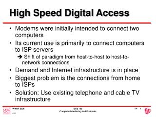
Motivation • FIR - Finite Impulse Response Filter • Fundamental processing unit in DSP systems • High frequency applications • Video imaging • Low power applications • Wireless communications
Brief Discussion on FIR Filters • An N-tap FIR filter can be described by: Tsample TM +TA Direct Implementation
2-parallel FIR Filter Parallel Processing Advantage Reduced power consumption Or high speed Disadvantage Overhead of area FIR Discussion contd. 2-parallel design
Why Pipelined/Parallel ? • Pipelined to enable higher sampling rates • Sampling frequency can be increased n-fold if we have n pipeline stages. • Parallel for low power
Why Pipelined/Parallel? Contd. - V can be decreased by - C increases by L (L=2) - f can be decreased by L
Optimizations at various levels Levels of design hierarchy Improvement Achieved
Full Adder • Dynamic Logic • True Single Phase Clocking (TSPC)
Baugh-Wooley Algorithm for 8 X 8 multiplication 2’s complement numbers Pipelined Multiplier
Latency of 12 cycles Partial product summing full adder array Vector merge adder Latch stages to skew the multiplier bits b0-b7 Deskewing latches for the product bits Pipelined Multiplier Floor Plan
Pipelined Multiplier contd. • Example • Input vectors 111111a1 X 0101010b • If a=1 and b=1 we have the following output sequence. • 1111111110101011
16 X 16 Pipelined Adder • Latency of 8 cycles • Triangular array of half adders • Merging of two half adder rows • Leads to decrease in latency • Advantage • Regularity of design • Fewer deskewing latches
Trouble Shooting • Convergence problems • Elmore/Penfield analysis requires lot of disk space and time