Download
1 / 24
250 likes | 898 Vues
Boxcar FIR Filter. Shadi Hawawini Pearl Yuan Amr Darwish Karun Malhotra Advisor: Dr. Parent May 8, 2006. Agenda. Abstract Introduction Why Simple Theory Background Information Summary of Results Project (Experimental) Details Results Cost Analysis Conclusions. Abstract.

E N D
Boxcar FIR Filter Shadi Hawawini Pearl Yuan Amr Darwish Karun Malhotra Advisor: Dr. Parent May 8, 2006
Agenda • Abstract • Introduction • Why • Simple Theory • Background Information • Summary of Results • Project (Experimental) Details • Results • Cost Analysis • Conclusions
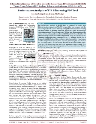
Abstract • We designed a 4-bit Finite Impulse Response (FIR) Filter that operates at 200 MHz • Impulse Response - A set of FIR coefficients, which represent all possible frequencies. • Tap - A coefficient/delay pair. The number of FIR taps is an indication of the amount of memory required to implement the filter.
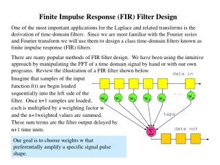
Introduction • One of the most fundamental elements for a DSP system is an FIR Filter. • There is no feedback, which results in a finite output value of zero. • The filter is mathematically expressed using the following difference equation:
FIR Block Diagram • The FIR Filter consist of three main components: • 1) A D Flip-Flop to implement a simple delay. • 2) A Multiplier to implement the coefficients, which in our case we are using a Boxcar filter, meaning all coefficients are 1. • 3) A Full adder to sum the nodes at the end of each Tap.
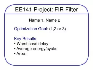
Cost Analysis • Estimated time spent on each phase of the project: • Verifying Logic = 2 weeks • Verifying Timing = N/A • Layout = 15 hours • Post Extracted Timing = 5 hours
Lessons Learned • A project of this nature requires ample time to complete it, before its deadline. • Verify logic of individual components. • Extra care needed when designing the layout.
Summary • Because FIR Filters are such an important element of DSP design, it was beneficial to do a project like this to strengthen understanding of the concept • A low cost, easy to implement Boxcar FIR filter was designed and tested • Due to the nature of DSP, FIR filters of some form will always be needed.
Acknowledgements • Dr. Parent, for teaching us not to overcomplicate our designs.