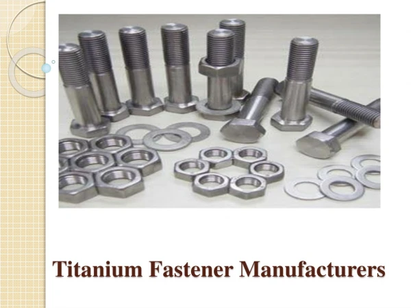
Tack Fastener Plans
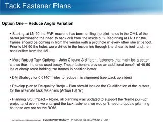
Tack Fastener Plans. Option One – Reduce Angle Variation

Tack Fastener Plans
E N D
Presentation Transcript
Tack Fastener Plans • Option One – Reduce Angle Variation • Starting at LN 90 the PAR machine has been drilling the pilot holes in the OML of the barrel (eliminating the need to back drill from the inside out). Beginning at LN 127 the frames should be coming in from the vendor with a pilot hole in every other shear tie foot. Prior to LN 90 the holes were drilled in the feederline through the shear tie feet and then back drilled from the IML. • More Robust Tack Options – John C found 3 different fasteners that might be a better choice than the ones used today. These fasteners provide an additional benefit of 40-50 lbs of clamp force holding the frames in position better • DM Strategy for 0.0140” holes to reduce misalignment (see back up slides) • Develop plan to Re-qualify Brotje – Plan should include the Qualification of the cutters for the alternate tack fasteners (Action Pat W) • Planning SOI/Impact – None, all planning was updated to support the “frame pull-up” project and even if we changed the tack fasteners we wouldn’t need to update planning as these are not on the BOM.
Tack Fastener Plans • Option Two – Replace Tacks with FS Fasteners • Additional time required in CS 260 – Current estimate is 39 hours, need to do a critical path analysis to determine if there are any producibility changes that would reduce the time • Time offset from Brotje ( Action Pat W) • Planning SOI/Impact (Action Shemeekia B)
Tack Fastener Plans • Option Three – Better Sync Capability on Brotje • Hole mismatch, tack height, skin thickness, syncing process and tack angularity contribute to the hole elongation by Brotje. A process that syncs on the OML center point eliminates the contribution of tack height, skin thickness and tack angularity. A Mylar target with a hole feature, cross hairs and concentric circles provide a sync point limiting the contributors to hole mismatch and gaps. Advantages to this method are short time to incorporate and small investment required acquire LUT’s. Disadvantages are the verifying the mylar is removed before fastener insertion and it does not address gap issues. Other methods that provide a sync point on the OML are tack installation with no tack height from the OML and automated SYNCing method that determines the OML point based on tack angularity.
Tack Fastener Plans • Plan Forward • Benchmark Spirit – Put together a list of list of items to talk with Spirit about. The list should include their current tack fasteners and what they have tried in the past
Section 47 Side Frames DA hole analysis Section 47 Section 47 Skin DA Holes Frame DA Holes DIA .123 to .128 Tack Fastener Current Risk
Tack OrientationEquation for final variation Vtackorientation tskin tframe Ɵ Htack Vholemismatch Assumption skin thickness is larger than frame shear tie thickness Xsyncvariation= Vtackorientation + Vholemismatch= (Htack - tskin- tframe) Vholemismatch/ tskin +Vholemismatch