Understanding Capacitors: Charge Storage and Capacitance Explained
290 likes | 424 Vues
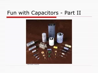
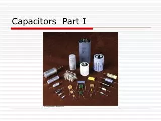
This article delves into the fundamental concepts of capacitors, describing their structure as two metal plates, one positively and one negatively charged. It explains how capacitors store charge and energy, emphasizing the role of applied voltage and capacitance. Detailed insights into plate area, separation, and the relationship between charge and electric field are provided, along with examples of capacitor circuits in series and parallel configurations. The significance of capacitance is highlighted with definitions and practical applications, especially in technologies like Random Access Memory (RAM).

Understanding Capacitors: Charge Storage and Capacitance Explained
E N D
Presentation Transcript
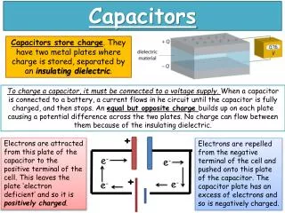
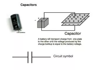
Capacitor • Composed of two metal plates. • Each plate is charged • one positive • one negative • Stores Charge SYMBOL
A simple Capacitor TWO PLATES WIRES Battery
d Air or Vacuum E - Q +Q Symbol Area A V=Potential Difference Two Charged Plates(Neglect Fringing Fields) ADDED CHARGE
Where is the charge? +++++ + - - - - - - d AREA=A s=Q/A Air or Vacuum E - Q +Q Area A V=Potential Difference
One Way to Charge: • Start with two isolated uncharged plates. • Take electrons and move them from the + to the – plate through the region between. • As the charge builds up, an electric field forms between the plates. • You therefore have to do work against the field as you continue to move charge from one plate to another. The capacitor therefore stores energy!
Capacitor Demo
d Air or Vacuum E - Q +Q Gaussian Surface Area A V=Potential Difference More on Capacitors Same result from other plate!
DEFINITION • The Potential Difference is APPLIED by a battery or a circuit. • The charge q on the capacitor is found to be proportional to the applied voltage. • The proportionality constant is C and is referred to as the CAPACITANCE of the device.
NOTE • Work to move a charge from one side of a capacitor to the other is qEd. • Work to move a charge from one side of a capacitor to the other is qV • Thus qV=qEd • E=V/d (Hold this thought.)
UNITS • A capacitor which acquires a charge of 1 coulomb on each plate with the application of one volt is defined to have a capacitance of 1 FARAD • One Farad is one Coulomb/Volt
Continuing… • The capacitance of a parallel plate capacitor depends only on the Area and separation between the plates. • C is dependent only on the geometry of the device!
Units of e0 pico
Simple Capacitor Circuits • Batteries • Apply potential differences • Capacitors • Wires • Wires are METALS. • Continuous strands of wire are all at the same potential. • Separate strands of wire connected to circuit elements may be at DIFFERENT potentials.
Size Matters! • A Random Access Memory stores information on small capacitors which are either charged (bit=1) or uncharged (bit=0). • Voltage across one of these capacitors ie either zero or the power source voltage (5.3 volts in this example). • Typical capacitance is 55 fF (femto=10-15) • Question: How many electrons are stored on one of these capacitors in the +1 state?
TWO Types of Connections SERIES PARALLEL
V CEquivalent=CE Parallel Connection
q -q q -q V C1 C2 Series Connection The charge on each capacitor is the same !
q -q q -q V C1 C2 Series Connection Continued
Example C1=12.0 uf C2= 5.3 uf C3= 4.5 ud C1 C2 series (12+5.3)pf (12+5.3)pf V C3
E=e0A/d +dq +q -q More on the Big C • We move a charge dq from the (-) plate to the (+) one. • The (-) plate becomes more (-) • The (+) plate becomes more (+). • dW=Fd=dq x E x d
Parallel Plate Cylindrical Spherical Not All Capacitors are Created Equal
Calculate Potential Difference V (-) sign because E and ds are in OPPOSITE directions.
Continuing… Lost (-) sign due to switch of limits.