Download
1 / 35
350 likes | 373 Vues
CAPACITORS Part I. February 12, 2007. Calendar of the Week. This week – Capacitors Watch for new WebAssign There will be a quiz on Friday. Capacitors Part I. Capacitor. Composed of two metal plates. Each plate is charged one positive one negative Stores Charge. SYMBOL.

E N D
CAPACITORS Part I February 12, 2007
Calendar of the Week • This week – Capacitors • Watch for new WebAssign • There will be a quiz on Friday
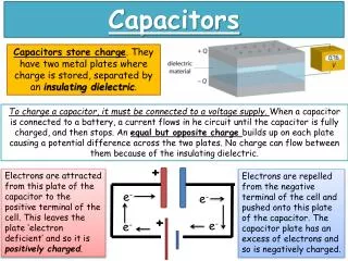
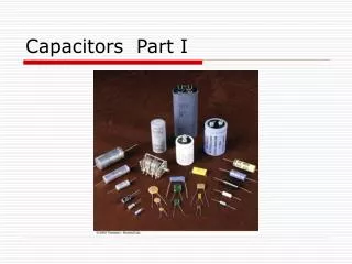
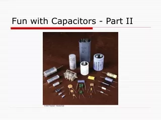
Capacitor • Composed of two metal plates. • Each plate is charged • one positive • one negative • Stores Charge SYMBOL
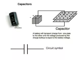
From Before: A simple Capacitor TWO PLATES WIRES Battery
What is STORED in the capacitor? • An Electric Field • Energy • Charge • All three • None of these
d Air or Vacuum E - Q +Q Symbol Area A V=Potential Difference Two Charged Plates(Neglect Fringing Fields) ADDED CHARGE
Where is the charge? +++++ + - - - - - - d AREA=A s=Q/A Air or Vacuum E - Q +Q Area A V=Potential Difference
One Way to Charge: • Start with two isolated uncharged plates. • Take electrons and move them from the + to the – plate through the region between. • As the charge builds up, an electric field forms between the plates. • You therefore have to do work against the field as you continue to move charge from one plate to another. The capacitor therefore stores energy!
Capacitor Demo
d Air or Vacuum E - Q +Q Gaussian Surface Area A V=Potential Difference More on Capacitors Same result from other plate!
DEFINITION - Capacity • The Potential Difference is APPLIED by a battery or a circuit. • The charge q on the capacitor is found to be proportional to the applied voltage. • The proportionality constant is C and is referred to as the CAPACITANCE of the device.
UNITS • A capacitor which acquires a charge of 1 coulomb on each plate with the application of one volt is defined to have a capacitance of 1 FARAD • One Farad is one Coulomb/Volt
IS THIS A CAPACITOR?? • Yes • No • You gotta be kidding
The two metal objects in the figure have net charges of +79 pC and -79 pC, which result in a 10 V potential difference between them. (a) What is the capacitance of the system? [7.9] pF(b) If the charges are changed to +222 pC and -222 pC, what does the capacitance become? [7.9] pF(c) What does the potential difference become?[28.1] V
After the switch is closed, how much charge passed through the capacitor? • C/V • V/C • CV • C+V V
NOTE • Work to move a charge from one side of a capacitor to the other is qEd. • Work to move a charge from one side of a capacitor to the other is qV • Thus qV=qEd • E=V/d As before
Continuing… • The capacitance of a parallel plate capacitor depends only on the Area and separation between the plates. • C is dependent only on the geometry of the device!
Units of e0 pico
Simple Capacitor Circuits • Batteries • Apply potential differences • Capacitors • Wires • Wires are METALS. • Continuous strands of wire are all at the same potential. • Separate strands of wire connected to circuit elements may be at DIFFERENT potentials.
Size Matters! • A Random Access Memory stores information on small capacitors which are either charged (bit=1) or uncharged (bit=0). • Voltage across one of these capacitors ie either zero or the power source voltage (5.3 volts in this example). • Typical capacitance is 55 fF (femto=10-15) • Question: How many electrons are stored on one of these capacitors in the +1 state?
TWO Types of Connections SERIES PARALLEL
V CEquivalent=CE Parallel Connection
q -q q -q V C1 C2 Series Connection The charge on each capacitor is the same !
q -q q -q V C1 C2 Series Connection Continued
Example C1=12.0 uf C2= 5.3 uf C3= 4.5 ud C1 C2 series (12+5.3)pf (12+5.3)pf V C3
E=e0A/d +dq +q -q More on the Big C • We move a charge dq from the (-) plate to the (+) one. • The (-) plate becomes more (-) • The (+) plate becomes more (+). • dW=Fd=dq x E x d
Parallel Plate Cylindrical Spherical Not All Capacitors are Created Equal
Calculate Potential Difference V (-) sign because E and ds are in OPPOSITE directions.
Continuing… Lost (-) sign due to switch of limits.