PLASTIC SECTIONAL MODULUS
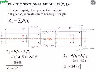
PLASTIC SECTIONAL MODULUS . Shape Property, Independent of material Higher indicates more bending strength. PNA. PNA. PNA. TOTAL. PNA (Plastic Neutral Axis). TOTAL. PNA (Plastic Neutral Axis). FULLY LOADED. FORCE X LEVERARM. For rectangular sections=. FORCE X LEVERARM.

PLASTIC SECTIONAL MODULUS
E N D
Presentation Transcript
PLASTIC SECTIONAL MODULUS • Shape Property, Independent of material • Higher indicates more bending strength PNA
TOTAL PNA (Plastic Neutral Axis)
TOTAL PNA (Plastic Neutral Axis)
FULLY LOADED FORCE X LEVERARM For rectangular sections=
LATERAL SUPPORT OF STEEL BEAMS 47 kip-ft CASE II CASE III CASE I W10X12 28.5 kip-ft CASE II CASE III CASE I
W10X12 BRACING DISTANCE CASE I if lateral brace is spaced 0-2.75’ CASE II if lateral brace is spaced 2.75’-8’ CASE III if lateral brace is spaced more than 8’ CASE I BRACES W10X12 Design Moment Strength = = 47 kip-ft
CASE II LATERAL BRACES W10X12 Design Moment Strength reduces as increases kip-ft AT AT kip-ft Linear variation in &
CASE III Should be avoided for load bearing floor beams. Design Moment Strength reduces as increases kip-ft AT AT kip-ft
CASE I CONSTRUCTION DETAILS x CONCRETE STEEL STUDS W-SHAPE X-X x Most Common Current Practice Using Metal Deck and Shear Studs. Steel and Concrete Deck can be designed as Composite or Non-Composite
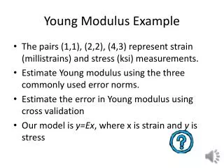
Use 50 ksi and select a shape for a typical floor beam AB. Assume that the floor slab provides continuous lateral support. The maximum permissible live load deflection is L/180. The service dead loads consist of a 5-inch-thick reinforced-concrete floor slab (normal weight concrete), a partition load of 20 psf, and 10 psf to account for a suspended ceiling and mechanical equipment. The service live load is 60 psf.
Fy = 50ksi • Case 1 GIRDER not to exceed • DEAD LOADS • 1) 5” Slab • 2) Partition = 20psf • 3) Ceiling, HVAC = 10psf • LIVE LOAD = 60psf GIRDER (PRIMARY BEAMS) Figure 1
DESIGN LOAD (kips/ft) on AB = wux TRIBUTORY AREA LENGTH OF BEAM x = 1.242 kips/ft 12” of Slab = 150 psf 6” of Slab = 75 psf 1” of Slab = 12.5 psf 5” of Slab = 62.5 psf (12.5 psf for every inch of concrete thickness) *5 x 12.5 = 62.5
wu = 1.242 kips/ft Mu = = = 139.7 ft-kips CASE 1
Page # 3-127 STRENGTH OF W14 X 26 = 150.7 ft-kips STRENGTH OF W16 X 26 = 165.7 ft-kips 139.7
Page # 1-21 SELECT W16X26
EXTRA SELF WEIGHT MOMENT = = 3.3 ft-kips MOMENT STRENGTH APPLIED MOMENT 165.7 139.7 + 3.3 W16X26 is OK = 2” = = = Page # 3-211
= 360 lb/ft w = = 0.360 kips/ft kips/in = 0.03 kips/in = = 0.75” 2” OK = in = ; =
Note that duct holes have to be strengthened by plates. Also, holes are at third point where shear & moment are not maximum. Typical Copes for a shear connection of a large girder to column web.
Cantilever construction for projected balcony. If shear studs are noticed on beams and column then those members have to be encased in concrete for increasing fire resistance of steel.