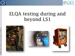
ELQA testing during and beyond LS1
ELQA testing during and beyond LS1. Overview. ELQA What? When? Why ? Tests: TP4, DOC, MIC, LS1 PAQ, AIV Sub-tests: IRC, ICC, ORC, TFM, BBC, HVQ 48V Insulation Monitoring Qualification Stages Equipment used for ELQA. ELQA: What, When and Why?. What is ELQA?

ELQA testing during and beyond LS1
E N D
Presentation Transcript
Overview • ELQA • What? When? Why? • Tests: • TP4, DOC, MIC, LS1 PAQ, AIV • Sub-tests: • IRC, ICC, ORC, TFM, BBC, HVQ • 48V Insulation Monitoring • Qualification Stages • Equipment used for ELQA
ELQA: What, When and Why? What is ELQA? • ELQA are the Electrical Quality Assurance activities which take place during technical stops and shutdowns of the LHC. When is ELQA performed? • ELQA campaigns are performed predominantly before and after thermal cycles of the LHC. They can, however, be performed after any form of testing or manipulation of electrical circuits of the LHC, in particular following the splice consolidation work. Why is ELQA performed? • ELQA tests are there to verify the continuity, configuration and integrity of the insulation of the LHC electrical circuits. It is an important process in finding any NC’s (Non Conformities) which are present in the LHC. Following any thermal cycles of the machine the electrical circuits must be ELQA qualified before powering can begin.
Main ELQA Tests • TP4 – Test Procedure 4(TP3/ TP2 & TP1 were performed during machine assembly) • HV and LV tests of circuits powered via DFBs • 743 circuits • DOC – Dipole Orbit Corrector check • HV and LV tests of circuits powered locally • 914 circuits • MIC – Magnet Instrumentation Check • HV and LV tests done locally on each magnet – it includes quench heater qualifications • 1763 magnets. • LS1 PAQ– Partial Qualification during Long Shutdown 1 • HV and LV test following the consolidation work (SMACC) • Up to 26 x 2 conductors in each sector; test is done on a daily basis. • AIV – Arc Interconnection Verification • LV test done after installation or replacement of magnets composing the continuous cryostat. Details of these tests are described on EDMS: 788197, 1269114, 1269127
Measurement details: IRC IRC – Instrumentation Resistance Check • To detect: • Open V-taps • Cold soldering • Bad contacts on the cable routing • Typically done using a 2-wire mode Ohm-meter or with a very little current (max 100mA) • This test is done in the frame of TP4, DOC and MIC tests PE Cable segment
Measurement details: ICC ICC – Instrumentation Continuity Check • To detect: • Swapped connectors • Swapped pins • Swaps in the PE (Proximity Equipment) or cable segment • Labelling problems • Cooling problems in current leads • It is done using a 4-wire method with a precision DVM and a DC current source • Max applied current is 3 A • This test is done in the frame of TP4 and DOC tests
Measurement details: ORC ORC – Ohmic Resistance Check • To detect: • Open circuit • At warm an abnormal resistance might mean • Short internal to the circuit • Wrong number of magnet coils • Wrongly connected bus-bars • At cold • Resistive circuit due to internal joints or cooling problems • Not independent - done together with the ICC test • This test is done in the frame of TP4 and DOC tests
Measurement details: TFM TFM – Transfer Function Measurement • To detect: • Open circuit • An abnormal inductance might mean • Short internal to the circuit or coil • Wrong number of magnet coils • Wrongly connected bus-bars • Gain-phase analyser is used together with a reference resistance and a power amplifier • Max 10 V AC • Max 1 A • Frequency sweep from 1 Hz to 100 kHz • This test is done in the frame of TP4 and DOC tests Gen.
Measurement details: BBC BBC – Bus-Bar Continuity check • To detect: • Open or highly resistive circuit • Circuit cross connected with another one • 4 wire method is used with a current source and a precision DVM • Max 500 mA • Max 24 V • This test is done in the frame of LS1 PAQ test M1 M2
Measurement details: HVQ HVQ – High Voltage Qualification • To detect: • Short circuit to ground or other circuits • Insulation degradation • DC voltage of max 2.1 kV • Output current limited by hardware to 2 mA • Leakage current measurement • Each circuit energised individually with respect to ground • All other circuits grounded • Voltages levels defined in HVQ ELQA database • Applied voltages different depending on thermal state • Safety precautions necessary • This test is done in the frame of TP4, DOC, MIC and LS1 PAQ tests
TP4-C During the warm-up and cool-down processes the insulation of main circuits is monitored • 48 V DC • Repetitively applied one by one to each circuit for 60 s • Early warning if thermal contraction leads to a short to ground • In some cases the short might disappear but the insulation is damaged
Measurement details: QHR QHR– Quench Heater Resistance measurement • To detect: • Open or abnormally resistive quench heater circuits • Semi 4-wire method • DC current 300 mA max. • Accuracy affected by contact resistances • This test is done in the frame of MIC test only IFS QH QH
Measurement details: AIV AIV – Arc Interconnection Verification • To detect: • Wrongly connected spool and line N bus-bars • Wrongly connected corrector magnets • Swapped V-taps • DC current of 300 mA • Used extensively during assembly of the machine • Will be reactivated for magnet replacement
Qualification Stages • The ELQA-TP4 procedures are composed of 4 stages. ELQA-DOC is performed at 2 stages. • Each stage has to be performed at a given temperature and pressure in the different cryogenic enclosures containing the superconducting circuits.
Equipment used for ELQA • HV crate • TP4 system For special diagnostics we have many devices that can be used in non standard configurations. Up to now these were used mainly during technical stops in the phase of operation.
TP4 system sketch • A set of 4 multiplexers allows • 4 wire resistance measurement in any configuration • Simultaneous measurement of two signals Device selector • The resistors are used for setting the working point of the power supply and for current measurement. • 18 Internal voltage taps are routed to the inputs of the multiplexers.
Statistical analysis tools Many tools exist already, some more still need to be developed.