Download
1 / 19
190 likes | 209 Vues
The R-FOFO snake channel is a rectilinear design with tilted solenoids and wedge absorbers, providing efficient 6D muon cooling. This text delves into the structure, characteristics, and applicability of the R-FOFO snake, comparing it to other designs like the Guggenheim channel. Detailed simulations, tracking, and cooling analyses are presented, offering insights into its performance and compatibility with different systems. Challenges and potential optimizations are also discussed for enhanced cooling capabilities.

E N D
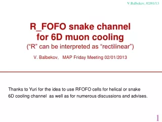
R_FOFO snake channel for 6D muon cooling (“R” can be interpreted as “rectilinear”) V. Balbekov, MAP Friday Meeting 02/01/2013 V.Balbekov, 02/01/13 Thanks to Yuri for the idea to use RFOFO cells for helical or snake 6D cooling channel as well as for numerous discussions and advises. 1
The R_FOFO “snake” is actually a rectilinear channel with tilted alternating solenoids and wedge absorbers. It is similar in appearance to the helical FOFO snake. However, use of wedge absorbers instead of planar ones essentially changes features and applicability. Substantially, the R_FOFO is closer to the Guggenheim channel because: - Both of them can be composed of identical cells being different only inarrangement of the parts; - They have almost the same characteristics (acceptance, ultimate beam emittance, transmission, etc.); At the same time, the R_FOFO snake is significantly simpler in construction. V.Balbekov, 02/01/13 Schematic of the R_FOFO snake View from above Guggenheim 35-50 mrad Helical FOFO snake 2
V.Balbekov, 02/01/13 R_FOFO snake with 2.75 m cells (Guggenheim cells by P. Snopok, G. Hanson, and A. Klier, IJMPA 24-5, 987, 2009) Cell schematic and field at X=Y=0 List of parameters Period length 275 cm Solenoids inclination ±35 mrad Maximal field strength on axis: longitudinal 2.80 T horizontal 0.13 T Maximal field strength in coil 7.22 T Current density 102 A/mm2 Reference momentum 210 MeV/c Accelerating frequency 200 MHz Accelerating gradient 13.5 MV/m Synchronous phase 25° Absorber LH2 thickness on axis 32 cm opening angle 78° 3
V.Balbekov, 02/01/13 Beta-function Beta-function at the absorber center against muon momentum. Working zone 155 MeV/c<P<245 MeV/c is bounded by integer and half-integer resonances. Phase advance is about 3π/2 per cell at the center of the working zone and it is less of π at P>275 MeV/c Beta-function at 210 MeV/c against longitudinal coordinate starting from the absorber center. Minimal beta is 40 cm 4
V.Balbekov, 02/01/13 Periodic orbit and dispersion Several periodic orbits are plotted against longitudinal coordinate starting from the absorber center. Muon momenta are 170-250 MeV/c, step10 MeV/c. Blue – horizontal, red – vertical. P=210 MeV/c is marked by green. Dispersion function against longitudinal coordinate staring from absorber center. Muon momenta are 170-240 MeV/c, step 10 MeV/c. Blue – horizontal, red – vertical. P=210 MeV/c is marked by green. Dx=−11 cm (Guggenheim – 8 cm) 5
V.Balbekov, 02/01/13 Tracking simulation (no stochastic effects) Betatron oscillations of a particle with momentum 210 MeV/c Synchrotron oscillations of a particle with 200 MHz RF and 210 MeV/c reference momentum. 6
V.Balbekov, 02/01/13 Cooling simulation without stochastic effects The parameters are chosen to get about equal cooling rates in all direction. Can be changed (optimized) by variation of the solenoid tilt and/or wedge absorber angle. Below: LH2 absorber shape (R_FOFO snake (filled) and Guggenheim) Guggenheim 7
V.Balbekov, 02/01/13 Cooling simulation with stochastic effects Table: beam parameters after 200 m (R_FOFO compared with Guggenheim) R_FOFO Gug Trans. emit. (mm) 3.6 3.7 Long. emit. (mm) 5.0 6.1 Transmission with decay (%) 54 62 Below: phase space in the beginning and after 275 m: X-Px, Y-Py, cT-ΔE (cm, MeV) 8
V.Balbekov, 02/01/13 Is it possible to cool muons of both signs together? • Horizontal periodic orbit and dispersion function do not depend on muon sign being directed by longitudinal solenoid field. • Vertical periodic orbit and dispersion function are placed symmetrically in accordance with muon sign. • Therefore opposite located and shaped wedge absorbers are needed for positive/negative muons. • Consequently, the R_FOFO snake is unfit for cooling of μ± simultaneously. • Planar absorbers would be needed for this like Yuri helical FOFO snake which is suitable for μ± • But HFOFO incompatible with RFOFO idea because the planar absorbers are placed where β-function is maximal. Challenge: How to include planar absorbers into a channel with strongly modulated beta-function for 6D cooling (???) Different absorbers needed for μ± 9
V.Balbekov, 02/01/13 Is R_FOFO compatible with Front-End system (325 MHz) 2.75 m cell is slightly modified Front-end beam distribution by D. Neuffer Accelerating frequency 200 → 325 MHz Reference momentum 210 → 245 MeV/c Accelerating gradient 13.5 → 20 MV/m Synchronous phase 25° → 30° Absorber thickness 32 cm → 34 cm Absorber angle 78° → 80° Current density 102 → 119 A/mm2 Long. field on axis 2.80 T → 3.40 T Hor. Field on axis 0.13 T → 0.15 T Maximal field in coil 7.22 T → 8.37 T Red – longitudinal distribution after collection of all particles of a butch in a single 325 MHz bunch. The separatrix is full, the bunch rms emittance is 2.7 cm. Maroon – any transverse distribution: X-Px, X-Py, etc. Emittance 0.34 cm It is a collimated distribution with LiH absorber 10
V.Balbekov, 02/01/13 Cooling simulation with 2.75 m/325 MHz R_FOFO Longitutinal cooling by the R_FOFO snake after front-end. Final emittances 0.4 cm in all directions, transmission 80%. Longitudinal phase space before and after the cooling. 11
V.Balbekov, 02/01/13 Is it possible to convert the Front-End 4D to 6D cooling channel? Front-End cell from David is used as basis The solenoids are inclined by ±50 mrad, and the absorbers are wedge-shaped List of parameters Period length 150 cm Maximal field strength on axis: longitudinal 2.78 T horizontal 0.17 T Maximal field strength in coil 7.25 T Current density 107 A/mm2 Solenoids inclination ±50 mrad Reference momentum 245 MeV/c Accelerating frequency 325 MHz Accelerating gradient 25 MV/m Synchronous phase 30° Absorber LH2 thickness on axis 17 cm opening angle 38° 12
V.Balbekov, 02/01/13 Modified FE channel: beta-function, periodic orbit, dispersion Beta-function vs momentum Weak parametric resonance appears at P=138 MeV/c Beta-function vs longitudinal coordinate Average beta is 86 cm, modulation ±4% Periodic orbit at 245 MeV/c. Horizontal orbit almost does not depend on momentum Dispersion function at 245 MeV/c. Horizontal dispersion is ≈0, vertical one is about -10 cm everywhere. 13
V.Balbekov, 02/01/13 Cooling by modified FE channel with tilted solenoids Phase space before and after the cooling. Left – horizontal, right – longitudinal. • Tilting of solenoids + wedge absorbers can transform 4D to 6D cooling channel. • It provides good longitudinal cooling and 90% transmission. • Modest growth of transverse emittance results from decrease of transverse decrement due to emittance exchange. • In principle, it allows to incorporate 6D cooling into front-end channel • It is unsuitable for simultaneous cooling of μ± but can be useful for ν-factory • Alexahin’s HFOFO snake looks as a better choice for μ±, because beta-function is not perceived to be very small in the phase rotation – precooling sections. 14
V.Balbekov, 02/01/13 B.Palmer & Rick Fernow, MAP Friday Meeting 10/26/12 15
V.Balbekov, 02/01/13 Cooling channel of less beta: lattice, field, other parameters Cell schematic and field at X=Y=0 List of parameters Period length 150 cm Maximal field strength on axis: longitudinal 4.98 T horizontal 0.34 T Maximal field strength in coil 7.71 T Current density 69/94A/mm2 Solenoids tilt ±50 mrad Reference momentum 210 MeV/c Accelerating frequency 400 MHz Accelerating gradient 22 MV/m Synchronous phase 30° Absorber LH2 thickness on axis 32 cm opening angle 78° 16
V.Balbekov, 02/01/13 Beta-function, periodic orbit, dispersion Beta-function vs muon momentum. Working zone is 165-255 MeV/c, Beta-function vs longitudinal coordinate. Minimal beta is 22 cm Periodic orbit at 200-210-220 MeV/c. Dispersion function at 210 MeV/c. Vertical dispersion at the absorber is -10.5 cm 17
V.Balbekov, 02/01/13 Cooling simulation Phase space before and after the cooling. Left – horizontal, right – longitudinal. Initial emittance 0.6 cm is accepted at all directions as the phase rotation – precooling channel can provide (hopefully) With the same absorber as previously (32 cm, 78°), equilibrium transverse emittance is about 1.8 mm which is coming with beta-function 22 cm. Without decay, transmission is 60% at 400 MHz RF (but it is 79% at 200 MHz). Violation of longitudinal motion due to dependence of particle time of flight on betarton amplitude is the main cause of the loss. Violation 18
Only the lenses are simulated. Ideal matrix is used instead of matching sections. Summary V.Balbekov, 02/01/13 • R_FOFO snake channel with tilted solenoids is usable for 6D cooling • Essentially, any FOFO or RFOFO 4D-cooling channel can be converted into 6D-channel by inclination of solenoids (typically on 30-60 mrad) and use of wedge absorbers • The R_FOFO is easy adjustable with front-end (phase rotation) channel for ν-factory. However, because of wedge absorbers, it is unsuitable for simultaneous cooling of μ± • As it is simulated, transverse emittance 1.8 mm and longitudinal one 2.4 mm are achievable with magnetic field 5 T in axis, 7.7 T in the coil. • Emittance less of 1 mm looks to be a realistic goal with magneic field 10-12 T in coils. • However, particles loss due to dependence of flying time on betatron amplitude is a serious constraining factor for transmission. Lower accelerating frequency is preferable from this point of view. 19