FOURIER TRANSFORM
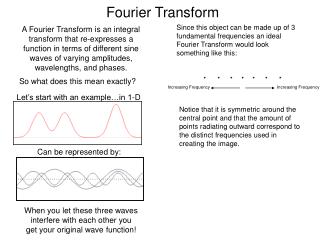
FOURIER TRANSFORM. FOURIER TRANSFORM – FOURIER TRANSFORM is used to analyse the signals in time as well as frequency domain. Frequency response of the system can also be studied with the help of Fourier transform.


FOURIER TRANSFORM
E N D
Presentation Transcript
FOURIER TRANSFORM BDG(51)
FOURIER TRANSFORM – • FOURIER TRANSFORM is used to analyse the signals in time as well as frequency domain. • Frequency response of the system can also be studied with the help of Fourier transform. • Analysis of some of the noise signals can also be performed in frequency domain with the help of Fourier transform. BDG(51)
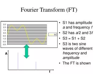
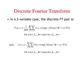
Definition of Fourier Transform – • The fourier transform of x(t) is defined as • X(ω) =ʃ x(t)e^-jωt dt (ʃ from - ∞ to + ∞) or • X(f) = ʃ x(t)e^-j2πftdt (ʃ from - ∞ to + ∞) • Where x(t) is time domain and X(ω) or X(f) is frequency domain signal representation. • X(ω) is also written as X(jω) sometimes. BDG(51)
Similarly x(t) can be obtained by inverse fourier transform – • IFT x(t) = 1/2π ʃ X(ω)e^jωt dω = ʃ X(f) e^ j2πftdf. (ʃ from - ∞ to + ∞) • A FT pair is represented as • X(t) - FT - X(ω) or x(t) – FT – X(f). BDG(51)
Existence of Fourier Transform – Dirichlet conditions - • 1. Single value property – x(t) must have only value at any time instant over a finite time interval T. • 2. Finite discontinuities – x(t) should have at the most finite number of discontinuities over a finite time interval T. • 3. Finite peaks – The signal x(t) should have finite number of maxima and minima over a finite time interval T. BDG(51)
4. Absolute integrability – x(t) should be absolutely integrable i.e. • ʃ І x(t) Іdt < ∞ (ʃ from - ∞ to + ∞) . • These conditions are sufficient but not necessary for the signal to be Fourier transformable. BDG(51)
Properties of Fourier Transform – • Let us consider following Fourier transform pairs – x(t) X(ω) and y(t) Y(ω) • 1. Linearity – The FT of linear combination of the signals is equal to linear combinations of their FT. ( Superposition). • z(t) = ax(t)+by(t) Z(ω) = aX(ω)+bY(ω) BDG(51)
2. Time Shift – A shift of “to” in time domain is equivalent to introducing a phase shift of (–)ωto. But amplitude remains same. • y(t) = x(t-to) FT Y(ω) = e^ -jωto X(ω). • 3. Frequency Shift – It states that by shifting the frequency by ‘β’ in frequency domain, is equivalent to multiplying the time domain signal by e^jβt. • y(t) =e^jβt x(t) FT Y(ω) = X(ω- β) BDG(51)
4. Time Scaling – Compression of signal in time domain is equivalent to expansion in frequency domain and vice-versa. • y(t) = x(at) FT Y(ω) = 1/ІaІ X(ω/a) • 5. Frequency Differentiation – Differentiating the frequency spectrum is equivalent to multiplying the time domain signal by complex number -jt. • -jt x(t) FT d/dω X(ω) BDG(51)
6. Time - differentiation – Differentiation in time domain corresponds to multiplying by jω in frequency domain. It accentuates high frequency components of the signal. • d x(t) / dt FT jωX(ω). • 7. Convolution – A convolution operation is transformed to modulation in frequency domain. • z(t) = x(t)*y(t) FT Z(ω) = X(ω). Y(ω) BDG(51)
8. integration – Integration in time represents smoothing in time domain. This smoothing in time corresponds to de-emphasizing the high frequency components of the signal. • ʃ x(τ)dτ FT δπ X(O) δ(ω) +1/jω X(ω) • (ʃ from - ∞ to t.) • 9. Modulation – Modulation in time domain corresponds to convolution of spectrums in frequency domain. • z(t) = x(t) y(t) FT Z(ω) = 1/2 π {X(ω)*Y(ω)} BDG(51)
10 Duality – X(t) FT 2π x(- ω). • 11 Symmetry – Let x(t) be a real signal and X(ω) = Xr(ω) +jXi(ω), then xe(t) FT Xr(ω ) and xo(t) FT jXi(ω) BDG(51)
NOISE BDG(51)
Noise is a general term which is used to describe an unwanted signal which affects a wanted signal. • These unwanted signals arise from a variety of sources which may be considered in one of two main categories:- • Interference, usually from a human source (man made) • Naturally occurring random noise which is inherently present in electronic communication systems from either ‘external’ sources or ‘internal’ sources. BDG(51)
With reference to an electrical system, noise may be defined as any unwanted form of energy which tends to interfere with proper reception and reproduction of wanted signal. • OR • Noise is random, undesirable electrical energy that enters the communications system via the communicating medium and interferes with the transmitted message. However, some noise is also produced in the receiver. BDG(51)
Correlated and uncorrelated Sources of Noise - • Correlated noise – Noise is correlated to the signal and it is present only when signal is present. Generated mainly because of non linear amplification, harmonic distortion and intermodulation distortion. • Harmonic distortion occurs when unwanted harmonics of a signal are produced through non linear amplification. • Intermodulation distortion is the generation of unwanted sum and difference of frequencies produced when two or more frequency signals are mixed in a non linear device. BDG(51)
Uncorrelated noise –Noise is present irrespective of the presence of signal. Mainly of Two types – External and Internal. BDG(51)
Classification of Noise – • Noise may be put into following two categories- • External noises, i.e. noise whose sources are external. • External noise may be classified into the following three types: • Atmospheric noises • Extraterrestrial noises • Man-made noises or industrial noises. BDG(51)
Internal noise in communication, i.e. noises which get, generated within the receiver or communication system. • Internal noise may be put into the following four categories. • Thermal noise or white noise or Johnson noise • Shot noise. • Transit time noise • Miscellaneous internal noise. BDG(51)
External noise cannot be reduced except by changing the location of the receiver or the entire system. • Internal noise on the other hand can be easily evaluated Mathematically and can be reduced to a great extent by proper design. • Because of the fact that internal noise can be reduced to a great extent, study of noise characteristics is a very important part of the communication engineering. BDG(51)
External Noise - Atmospheric Noise • Atmospheric noise or static is caused by lighting discharges in thunderstorms and other natural electrical disturbances occurring in the atmosphere. • These electrical impulses are random in nature. • Hence the energy is spread over the complete frequency spectrum used for radio communication. • Atmospheric noise accordingly consists of spurious radio signals with components spread over a wide frequency range. BDG(51)
These spurious radio waves constituting the noise get propagated over the earth in the same fashion as the desired radio waves of the same frequency. Accordingly at a given receiving point, the receiving antenna picks up not only the signal but also the static from all the thunderstorms, local or remote. • The field strength of atmospheric noise varies approximately inversely with the frequency. BDG(51)
Extraterrestrial Noise • There are numerous types of extraterrestrial noise or space noises depending on their sources. • However, these may be put into following two subgroups. • Solar noise • Cosmic noise BDG(51)
Solar Noise • Thisis the electrical noise emanating from the sun. • Under quite conditions, there is a steady radiation of noise from the sun. • This results because sun is a large body at avery high temperature (exceeding 6000°C on the surface), and radiates electrical energy in the form of noise over a very wide frequency spectrum including the spectrum used for radio communication. BDG(51)
The intensity produced by the sun varies with time. • In fact, the sun has a repeating 11-Year noise cycle. • During the peak of the cycle, the sun produces some amount of noise that causes tremendous radio signal interference, making many frequencies unusable for communications. • During other years. the noise is at a minimum level. BDG(51)
Cosmic noise • Distant stars are also suns and have high temperatures. • These stars, therefore, radiate noise in the same way as our sun. • The noise received from these distant stars is thermal noise (or black body noise) and is distributing almost uniformly over the entire sky. We also receive noise from the centre of our own galaxy (The Milky Way) from other distant galaxies and from other virtual point sources such as quasars and pulsars. BDG(51)
Man-Made Noise (Industrial Noise) • By man-made noise or industrial- noise is meant the electrical noise produced by such sources as automobiles and aircraft ignition, electrical motors and switch gears, leakage from high voltage lines, fluorescent lights, and numerous other heavy electrical machines. • Such noises are produced by the arc discharge taking place during operation of these machines. Such man-made noise is most intensive in industrial and densely populated areas. BDG(51)
Internal Noise in communication • Thermal Noise • Conductors contain a large number of 'free" electrons and "ions" strongly bound by molecular forces. • The ions vibrate randomly about their normal (average) positions, however, this vibration being a function of the temperature. • Continuous collisions between the electrons and the vibrating ions take place. Thus there is a continuous transfer of energy between the ions and electrons. BDG(51)
This is the source of resistance in a conductor. The movement of free electrons constitutes a current which is purely random in nature and over a long time averages zero. There is a random motion of the electrons which give rise to noise voltage called thermal noise. • Thus noise generated in any resistance due to random motion of electrons is called thermal noise or white or Johnson noise. BDG(51)
The analysis of thermal noise is based on the Kinetic theory. • It shows that the temperature of particles is a way of expressing its internal kinetic energy. • Thus "Temperature" of a body can be said to be equivalent to the statistical rms value of the velocity of motion of the particles in the body. • At -273°C (or zero degree Kelvin) the kinetic energy of the particles of a body becomes zero. • Thus we can relate the noise power generated by a resistor to be proportional to its absolute temperature. BDG(51)
Noise power is also proportional to the bandwidth over which it is measured. • Pn ∝ TBPn = KTB ------ (1) Where • Pn = Maximum noise power output of a resistor.K = Boltzmann’s constant = 1.38 x10^-23 joules/degrees Kelvin. T = Absolute temperature.B = Bandwidth over which noise is measured. BDG(51)
From equation (1), an equivalent circuit can be drawn as shown in figure BDG(51)
From equation (2), we see that the square of the rms noise voltage is proportional to the absolute temperature of resistor, the value of the resistor, and the bandwidth over which it is measured. • En is quite independent of the Frequency. • Example • R.F. amplifier is having an input resistor of 8Kr and works in the frequency range of 12 to 15.5 MHz. Calculate the rms noise voltage at the input to this amplifier at an ambient temperature of 17oC? BDG(51)
Shot Noise • The most common type of noise is referred to as shot noise which is produced by the random arrival of electrons or holes at the output element, at the plate in a tube, or at the collector or drain in a transistor. • Shot noise is also produced by the random movement of electrons or holes across a PN junction. BDG(51)
Even through current flow is established by external bias voltages, there will still be some random movement of electrons or holes due to discontinuities in the device. • An example of such a discontinuity is the contact between the copper lead and the semiconductor materials. • The interface between the two creates a discontinuity that causes random movement of the current carriers. BDG(51)
Transit Time Noise • Another kind of noise that occurs in transistors is called transit time noise. • Transit time is the duration of time that it takes for a current carrier such as a hole or electron to move from the input to the output. • The devices themselves are very tiny, so the distances involved are minimal. • Yet the time it takes for the current carriers to move even a short distance is finite. At low frequencies this time is negligible. BDG(51)
But when the frequency of operation is high and the signal being processed is the magnitude as the transit time, then problem can occur. • The transit time shows up as a kind of random noise within the device, and this is directly proportional to the frequency of operation. BDG(51)
MISCELLANEOUS INTERNAL NOISES - Flicker Noise • Flicker noise or modulation noise is the one appearing in transistors operating at low audio frequencies. • Flicker noise is proportional to the emitter current and junction temperature. • However, this noise is inversely proportional to the frequency. Hence it may be neglected at frequencies above about 500 Hz and it, therefore, possess no serious problem. BDG(51)
Transistor Thermal Noise • Within the transistor, thermal noise is caused by the emitter, base and collector internal resistances. Out of these three regions, the base region contributes maximum thermal noise. • Partition Noise • Partition noise occurs whenever current has to divide between two or more paths, and results from the random fluctuations in the division. It would be expected, therefore, that a diode would be less noisy than a transistor (all other factors being equal) if the third electrode draws current (i.e.., the base current). BDG(51)
Signal to Noise Ratio. • Noise is usually expressed as a power because the received signal is also expressed in terms of power. By Knowing the signal to noise powers the signal to noise ratio can be computed. Rather than express the signal to noise ratio as simply a number, it is expressed in terms of decibels. BDG(51)
A receiver has an input signal power of l.2µW. The noise power is 0.80µW. • The signal to noise ratio is • = 10 Log (1.2/0.8) = 10 log 1.5= 10 (0.176)= 1.76 dB BDG(51)
Noise Figure • Noise Figure F is designed as the ratio of the signal-to-noise power at the input to the signal to noise power at the output. • The device under consideration can be the entire receiver or a single amplifier stage. The noise figure F also called the noise factor can be computed with the expression • F = Signal to Noise power Input/Signal to noise power output • You can express the noise figure as a number, but more often you will see it expressed in decibels. BDG(51)
The noise factorF of a system is defined as • where SNRin and SNRout are the input and output signal-to-noise ratios, respectively. • The noise figure NF is defined as: • where SNRin, dB and SNRout, dB are in decibels (dB). BDG(51)
The noise factor of a device is related to its noise temperatureTe BDG(51)
If several devices are cascaded, the total noise factor can be found with Friis' Formula BDG(51)
where Fn is the noise factor for the n-th device and Gn is the power gain (linear, not in dB) of the n-th device. • The first amplifier in a chain has the most significant effect on the total noise figure than any other amplifier in the chain. • The lower noise figure amplifier should usually go first in a line of amplifiers (assuming all else is equal). BDG(51)
Note that when calculating cascaded noise figure, quantities must be expressed as ratios, NOT as decibels. • By convention, lower case variables represent ratios, while upper case variables represent decibels (dB). • Conversions: nf = 10NF/10 ↔ NF (dB) = 10 * log10 (nf) BDG(51)