Download
1 / 18
180 likes | 341 Vues
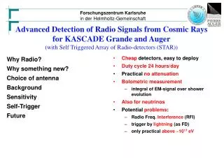
Advanced Detection of Radio Signals from Cosmic Rays for KASCADE Grande and Auger (with Self Triggered Array of Radio-detectors (STAR)). Cheap detectors, easy to deploy Duty cycle 24 hours/day Practical no attenuation Bolometric measurement integral of EM-signal over shower evolution

E N D
Advanced Detection of Radio Signals from Cosmic Rays for KASCADE Grande and Auger(with Self Triggered Array of Radio-detectors (STAR)) • Cheap detectors, easy to deploy • Duty cycle 24 hours/day • Practical no attenuation • Bolometric measurement • integral of EM-signal over shower evolution • Alsofor neutrinos • Potential problems: • Radio Freq. Interference (RFI) • trigger by lightning (as FD) • only practical above ~1017 eV Why Radio? Why something new? Choice of antenna Background Sensitivity Self-Trigger Future
Choice of antenna for STAR a. requirements: • bandwidth: 40 MHz to 80 MHz • good polarisation detection: north-south, east-west, circular • beam width (-3dB): -60°. . . +60° (at Karlsruhe), -80°...+80° (at Auger) • high 90° and backwardattenuation • reasonable precision for • impedance: frequency independent -> real • simple calibration • bull-proof, wind-proof,low cost, simple assembly • b. Considered antennas • V-dipole (LOFAR) • Logarithmic periodic conical helix (CODALEMA) • Logarithmic periodic dipole antenna (STAR) Hartmut Gemmeke, IPE, ARENA 2005
l/2 h What I know about LOPES V-dipole • f[MHz] 40 ... 80 • [m] 7.5... 3.75 • l/ < 1/4 • Impedance 55MHz 12.5 - j 150 • impedance matching to keep best timing information • reflectivity r: Bothe 45-> |r| > 50%, ??? precision & sensitivity ??? • this antenna is optimized for LOFAR but not for STAR? h =/8, b) h =/4, c) h =3/8, d) h =/2 For straight dipole over ground, depends on of ground and f !!! Hartmut Gemmeke, IPE, ARENA 2005
Logarithmic periodic antennas • Conical helix (tested also at Ka)Large Helix, 4 x 4 x 5 m3, nice: • more complicated to build and • crosstalk between both polarisations -> no further considerations • Surviving: Logarithmic periodic dipole antenna (LPDA) Hartmut Gemmeke, IPE, ARENA 2005
Crossed logarithmic-periodic Dipole Antenna 2 identical LPDAs mounted orthogonally on a shared pole <-> 2 polarizations Bandwidth: 35…90 MHz Gain: 5.5 dBi Impedance: 50 Ohm Coax Return loss: - 12 dB Beam width [-3dB]: 50° (E-Plane) 70° (H-Plane) Backward attenuation: 20 dB ± 90°-attenuation: 20 dB (E-Plane) 6 dB (H-Plane) Polarisation isolation: > 20 dB Size (without pole): 4 x 4 x 3 m3 Weight (without pole): 15 kg Lightning protection preamplifier Antenna Station on IPE building (south) Hartmut Gemmeke, IPE, ARENA 2005
E-Plane directional diagram of LPDA Beam width [-3 dB]: 50° Backward attenuation: 20 dB 90°-attenuation: > 20 dB Hartmut Gemmeke, IPE, ARENA 2005
H-Plane directional diagram of LPDA Beam width [-3 dB]: 70° Backward attenuation: > 15 dB 90°-attenuation: 6 dB Hartmut Gemmeke, IPE, ARENA 2005
Return loss of LPDA Real impedance Return loss (50 ): < -12 dB 94 % of the antenna signal power accepted by receiver Hartmut Gemmeke, IPE, ARENA 2005
Why not V-Dipol V-dipol Capacitive impedance difficult matching r > 50% -> don’t match: current f-dependance Very simple to build but not for the case top on a pole (ground plane) High wind-load at 200km/h? Bad side & backward attenuation -> needs a well defined ground plane Polarisation needs good calibration from antenna to antenna Logarithmic-Periodic Dipole Antenna Real impedance 60 simple matching very small reflectivity r < 10% (<12dB) negligible f-dependance Simple to build also on top of a pole Low wind-load at 200km/h Very good side & backward attenuation(necessary because of noise from surface detectors of Auger) -> needs not a well defined ground plane Relative calibration is mostly given by construction -> polarisation measurement easy Hartmut Gemmeke, IPE, ARENA 2005
20 dB NF 1,8dB 20 dB NF 1,8dB LNA-Supply LNA-Supply 40 MHz 8th order 40 MHz 8th order 80 MHz 8th order 80 MHz 8th order 40 MHz 8th order 40 MHz 8th order 80 MHz 8th order 80 MHz 8th order ± 0,4 V ± 0,4 V ± 0,4 V 20 dB 20 dB 20 dB 20 dB ± 0,4 V Rectifier Rectifier RG214 100 m radio frequency BIAS-T BIAS-T BIAS-T BIAS-T pos. envelope neg. envelope Crossed LPDA RG214 100 m radio frequency pos. envelope neg. envelope ADCs 20 dB NF 1,8dB RG214 100 m LNA-Supply 40 MHz 8th order 80 MHz 8th order 40 MHz 8th order 80 MHz 8th order radio frequency ± 0,4 V ± 0,4 V 20 dB 20 dB Rectifier pos. envelope Crossed LPDA BIAS-T BIAS-T neg. envelope 20 dB NF 1,8dB RG214 100 m LNA-Supply 40 MHz 8th order 80 MHz 8th order 40 MHz 8th order 80 MHz 8th order radio frequency ± 0,4 V ± 0,4 V 20 dB 20 dB Rectifier pos. envelope BIAS-T BIAS-T neg. envelope CH 5 20 dB Dual LNA NF 1.8 dB 3,3V (22mW/Channel) 1 Vpp / 50 Ohm CH 6 CH 7 CH 8 Analog RF Front End From antenna to ADC 50 ohm design VME, 6HE/160mm, 8 Channels, 3.3V(160mA),65mW/Channel Hartmut Gemmeke, IPE, ARENA 2005
Filtering and Amplification Band-pass Filter 32th order ! Pass-band Gain (41…79 MHz): + 55 dB Loss by 100m cable - 5 dB Ripple (41…79 MHz): ± 3 dB Slope: 10 dB/MHz Stop-band Short Wave Attenuation: -110 dB FM Radio Attenuation: - 90 dB VHF Attenuation - 80 dB Hartmut Gemmeke, IPE, ARENA 2005
Short Wave FM Radio VHF TV TV Transm. Raichberg Airplane Amateurs Police 32th order band pass filter Filtered Antenna Signal with Crossed LPDA FM radio, short wave and VHF are well rejected by the band-pass filter (32th order) Within 40…80 MHz band an ARD TV Transmitter is located: • Raichberg, Schwäbische Alb • ARD, channel E04, 100 kW • Video carrier: 62,25 MHz • Audio carrier: 67,75 MHz • with V-Dipol (LOPES) 10 dB larger interference signal Hartmut Gemmeke, IPE, ARENA 2005
Radio background at Auger20 to30 dB better than at Karlsruhe !!! Hartmut Gemmeke, IPE, ARENA 2005
AD-Conversion and circular buffer (test system) • Self designed ADC- and Circular-Buffer-System planed until end of 2005 • Standard VME DAQ-System • 16 Channels, 12 Bit, 80 MSample/s • Circular Buffer, 2 x 128 kSample/Channel (trigger = freeze) • Data Transfer, optical VME-PCI Interface Hartmut Gemmeke, IPE, ARENA 2005
Self trigger: Coincidence of three antennas Pulses from the horizon ( = 90°, interference sources) have a delay of: T ≥ h / c = 190 nsproblem: if source of interference is inside the triangle !! Pulses with higher elevation < 80 (e.g. from air showers)reach the antennas more simultaneously: 0 < T < 190 ns 65 m h = 56 m Envelope A1 + Mono-Flop 190 ns THR - Envelope A2 + Mono-Flop 190 ns = 3 THR - human made Interference from the horizon Envelope A3 + Mono-Flop 190 ns THR - Hartmut Gemmeke, IPE, ARENA 2005
RF Signal 20 mV Envelope 5 mV 200 ns Triggering with envelope signals • Envelope signals are generated by the analog RF front end • Advantage: • continuous RF -> shift of DC offset and -> easily rejected • Threshold 20mV: • Single rate KA < .2 Hz • Coincidence rates mHz Hartmut Gemmeke, IPE, ARENA 2005
north east south 200 ns 10 mV north + east + south but T > 190 ns no trigger Sensitivity Usable threshold 10 mV Radio field-strength: Hartmut Gemmeke, IPE, ARENA 2005
Calibration, GPS,DAQ-Container near to a power-line at Loma Amerilla Future: Test-field for Auger North l • Installation of several triangle LPDA setups in Argentina (shifted to Oct. 2006, financial situation), optimize l,L between 65 to 800 m • Detailed proposal at next spring • Radio will give very useful comple-mentary information: Energy • Self trigger is possible • choice of antenna may limit the obtainable E-resolution • radio is a cost-effective option for • Auger S&N • detector for space weather • But is also an excellent lightning detector (as Fluorescence Detector) … L Hartmut Gemmeke, IPE, ARENA 2005