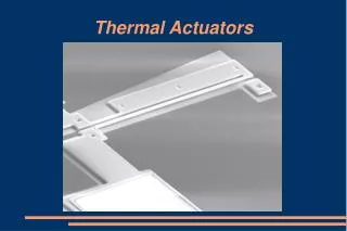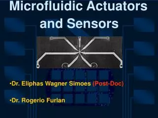
Thermal actuators
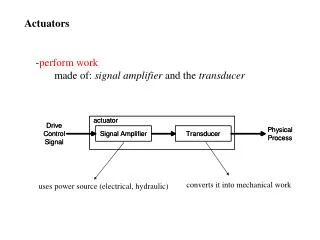
Thermal actuators. Give qualitative and quantitative descriptions of the three modes of heat transfer . Explain the behavior of a hot arm actuator, both qualitatively and quantitatively, based on our simplified lumped element model. A generic thermal actuator.

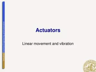
Thermal actuators
E N D
Presentation Transcript
Thermal actuators • Give qualitative and quantitative descriptions of the three modes of heat transfer. • Explain the behavior of a hot arm actuator, both qualitatively and quantitatively, based on our simplified lumped element model.
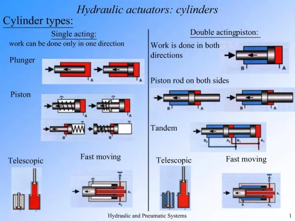
A generic thermal actuator Inside the actuator energy has been converted to the thermal mode. Thermal energy moves from regions of high temperature to low temperature. This is called heat transfer. Thermal actuator electrical input mechanical output (motion) waste thermal energy TH TL
The three modes of heat transfer TL TH Conduction Both require a material medium Convection (Conduction + advection) Does not require a material medium Radiation
Working equations of the three modes Conduction T1 T2 e2 e1 T1 T2 A TL TH 401 0.04 148
surface area A at Ts moving fluid at T∞ Working equations of the three modes Convection T2 T1 TL TH 2-20 10-1000 20-250 100-20,000
surface area A at Ts Working equations of the three modes Radiation Perfect blackbody Non-ideal surface TL TH 0.04 0.98 0.90 0.67 surrounding surfaceat Tsurr Small object completely surrounded by large surface
Repaso del actuador térmico Actuadortérmico (brazocaliente) ~ 200 μm Actuadortérmicohecho de polisilicio
Actuadortérmico Como funciona el actuador + e - i
Modelo sencillo de actuador térmico voltage tip deflection Thermal actuator electrical input mechanical output (motion) ωtip = f(e) Our goal: waste thermal energy ωtip + e -
Tetoca a ti Ideas on modeling List some ideas about how you might create such a model. What physical concepts would you use? What simplifications would you make? • Assume actuator has only two arms (hot arm and cold arm) each with only one temperature • The actuator is at steady state with a continuous electrical input being dissipated in the two electrical resistances created by the hot arm and the cold arm. • All the stress is initially experienced by the hot arm, which can be calculated in a way similar to thermal mismatch stress. • The hot arm stress causes a bending moment in the cold arm, the deflection of which can be calculated using standard beam bending theory. (Bernoulli beam bending)
hot arm at Th cold arm at Tc L Modelo sencillo de actuador térmico Perimeter, P Ah D Ac side view + eh - + e - I - ec +
hot arm at Th cold arm at Tc L Modelo sencillo de actuador térmico Perimeter, P Tetoca a ti Ah Find the voltage drops across the hot arm and cold arm (eh and ec) in terms of the input voltage (e), the resistivity of the actuator material (ρ), and its geometry. D Ac side view + eh - + e - i - ec +
hot arm at Th cold arm at Tc L Modelo sencillo de actuador térmico Perimeter, P Tetoca a ti Ah Find the temperatures the hot arm and cold arm (Th and Tc) in terms of the input voltage (e), the resistivity of the actuator material (ρ), its geometry, and the heat transfer coefficient (h). D Ac side view + eh - A = PL + e - i - ec +
x Modelo sencillo de actuador térmico Hot arm thermal stress σ Hot arm is initially at T∞, and is then heated to Th. What is the thermal strain? D ωtip Induced bending moment M ≈ DσAh What about the cold arm? Cold arm is much thicker than hot arm. So let’s assume both experience the same actual strain. Which one? εboth = εh or εc ? hot arm The ______ ______ experiences two pieces of strain – one due to thermal expansion and another extra piece due to the fact that it is hooked to the ______ ______. cold arm
x Modelo sencillo de actuador térmico Hot arm thermal stress σ Solve for this extra piece of strain, εextra. D ωtip Induced bending moment M ≈ DσAh How would you model the stress/strain in the hot arm? What would the relation for strain be, then? Is the arm in tension or compression?
Modelo sencillo de actuador térmico Beam bending relations dx x For small deflections dx ≈ ds, hence dx ≈ Rdθ. So ω ds θ dθ R For small deflections tan(θ)≈θ. Can also show
x Modelo sencillo de actuador térmico Hot arm thermal stress σ This gives us an expression for the deflection as a function of the length, x. D ωtip Induced bending moment M ≈ DσAh Integrate this expression from x = 0 to x = Lto get the tip deflection, ωtip. Finally, substitute expressions for σ and the temperatures to complete our model. ¡E no está!
Modelo un poco más complejo Add a third resistor fortheflexure:
Modelo un poco más complejo Electrical resistances of the arms given by Allow for a temperature dependence of resistivity, ρ = ρ(T):
Modelo un poco más complejo Comparison to the model of Huang and Lee (1999) ourmodel Q. A. Huang and N. K. S. Lee, “Analysis and design of polysilicon thermal flexure actuator,: J. Micromech. Microeng., vol. 9, pp. 64–70, 1999
Modelo un poco más complejo Mechanical model x
Modelo un poco más complejo Comparison to data Lc = 120 μm Lh= 240 μm Lc = 180 μm Lh= 240 μm
Modelo un poco más complejo Comparison to data Lc = 120 μm Lh= 240 μm Lc = 120 μm Lh= 240 μm E = 10 Pa E = 150 GPa