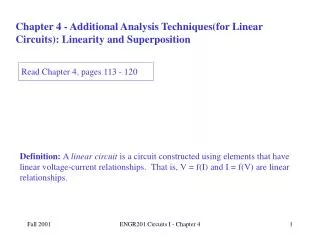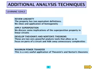
Additional Analysis Techniques for Linear Circuits
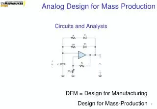
This book explores advanced analysis techniques and equivalent circuits for linear circuits, providing insights into circuit models and design. The author, Kevin D. Donohue from the University of Kentucky, covers topics such as superposition, equivalent circuits, source transformation, and more. With various examples and SPICE simulations, this resource helps readers understand the relationships between different circuit elements and optimize circuit performance.

Additional Analysis Techniques for Linear Circuits
E N D
Presentation Transcript
Additional Analysis Techniques for Linear Circuits Models and Equivalent Circuits for Analysis and Design Kevin D. Donohue, University of Kentucky
2A 4 6 Io 2 6 2A 4 4 6 Io 2 6 6 Io 9V 2 6 9V Example - Superposition • Solve for Io in the 3 circuits. What is the relationship between these results. Kevin D. Donohue, University of Kentucky
Linearity and Superposition • If a linear circuit has multiple independent sources, then a voltage or current quantity anywhere in the circuit is the sum of the quantities produced by the individual sources (i.e. the result when all other sources are deactivated). This property is called superposition. • To deactivate a voltage source, set the voltage equal to zero (equivalent to replacing it with a short circuit). • To deactivate a current source, set the current equal to zero (equivalent to replacing it with an open circuit). Kevin D. Donohue, University of Kentucky
Examples • Solve for voltages and currents in circuits containing multiple sources using the principle of superposition. Kevin D. Donohue, University of Kentucky
Example - Equivalent Circuit • Find the voltage and currents generated in 3 different loads across terminals AB: • open circuit • resistor RL • short circuit A Is Rth B A Rth Vs B Kevin D. Donohue, University of Kentucky
Results - Equivalent Circuit Current Source Circuit Voltage Source Circuit What would the value of the voltage source have to be so it is equivalent to the current source circuit? What would the value of the current source have to be so it is equivalent to the voltage source circuit? Kevin D. Donohue, University of Kentucky
Equivalent Circuits • Circuits containing different elements are equivalent, if their response with respect to (wrt) a pair of terminals is the same. • For the two previous circuits to be equivalent, what would have to be true about their source and resistance values? Kevin D. Donohue, University of Kentucky
A Is B Source Transformation • The following circuit pairs are equivalent wrt to terminals AB. Therefore, these source and resistor combinations can be swapped in a circuit without affecting the voltages and currents in other parts of the circuit A A A A Rth Rth Rth Vs Is Rth Rth Is B B B B A A A Rth Vs Vs Is B B B Kevin D. Donohue, University of Kentucky
Source Transformation • Some equivalent circuits can be determined by transforming source and resistor combinations and combining parallel and serial elements around a terminal of interest. • This method can work well for simple circuits with source-resistor combinations as shown on the previous slide. • This method is limited, if dependent sources are present. Kevin D. Donohue, University of Kentucky
Examples - Source Transformation • For several circuits find voltages and currents in circuits with independent sources and resistors using the method of source transformation. Kevin D. Donohue, University of Kentucky
Thévenin Equivalent Circuits • Find the value for Vth and Rth so the two circuits will be equivalent at terminals AB. + VA - A A Rth Vs 2 2 + Vo - B 12V 2 2 VA B Kevin D. Donohue, University of Kentucky
Norton Equivalent Circuits • Find the value for In and Rth so the two circuits will be equivalent at terminals AB. A + VA - A 2 Rth In 2 + Vo - 12V B 2 2 VA B Kevin D. Donohue, University of Kentucky
Finding Thévenin and Norton Equivalent Circuits • Identify terminal pair around which to find the equivalent circuit. • Find voltage across the terminal pair when no load is present (open-circuit voltage Voc) • Short the terminal and find the current in the short (short-circuit current Isc) • Compute equivalent resistance as: Rth = Voc / Isc Kevin D. Donohue, University of Kentucky
Finding Thévenin and Norton Equivalent Circuits • The equivalent circuits can then be expressed in terms of these quantities A A Rth Voc Rth Isc B B Kevin D. Donohue, University of Kentucky
Examples -Finding Equivalent Circuits • Find the Thévenin and Norton equivalents for circuits containing independent and dependent sources and resistors. • Show that for a maximum power transfer from a circuit to a load resistor, it must equal the Thévenin resistance of the circuit. Kevin D. Donohue, University of Kentucky
SPICE Examples • Find the Thévenin and Norton equivalents for circuits containing independent and dependent sources and resistors. • Show that for a maximum power transfer from a circuit to a load resistor, it must equal the Thévenin resistance of the circuit. Kevin D. Donohue, University of Kentucky