EC1313 – LINEAR INTEGRATED CIRCUITS
EC1313 – LINEAR INTEGRATED CIRCUITS. Name : M.Venmathi Designation: Senior Lecturer Department: Electrical and Electronics Engineering College: Rajalakshmi Engineering College. UNIT-I IC FABRICATION. INTEGRATED CIRCUITS.


EC1313 – LINEAR INTEGRATED CIRCUITS
E N D
Presentation Transcript
EC1313 – LINEAR INTEGRATED CIRCUITS Name : M.Venmathi Designation: Senior Lecturer Department: Electrical and Electronics Engineering College: Rajalakshmi Engineering College
UNIT-I IC FABRICATION
INTEGRATED CIRCUITS An integrated circuit (IC) is a miniature ,low cost electronic circuit consisting of active and passive components fabricated together on a single crystal of silicon. The active components are transistors and diodes and passive components are resistors and capacitors.
Advantages of integrated circuits Miniaturization and hence increased equipment density. Cost reduction due to batch processing. Increased system reliability due to the elimination of soldered joints. Improved functional performance. Matched devices. Increased operating speeds. Reduction in power consumption
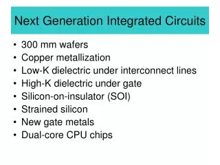
Basic processes involved in fabricating Monolithic ICs 1. Silicon wafer (substrate) preparation 2. Epitaxial growth 3. Oxidation 4. Photolithography 5. Diffusion 6. Ion implantation 7. Isolation technique 8. Metallization 9. Assembly processing & packaging
Silicon wafer (substrate) preparation 1.Crystal growth &doping 2.Ingot trimming & grinding 3.Ingot slicing 4.Wafer policing & etching 5.Wafer cleaning Typical wafer
Epitaxial growth Epitaxy means growing a single crystal silicon structure upon a original silicon substrate, so that the resulting layer is an extension of the substrate crystal structure. The basic chemical reaction in the epitaxial growth process of pure silicon is the hydrogen reduction of silicon tetrachloride. 1200oC SiCl+ 2H <-----------> Si + 4 HCl
Oxidation 1.SiO2 is an extremely hard protective coating & is unaffected by almost all reagents except by hydrochloric acid. Thus it stands against any contamination. 2. By selective etching of SiO2, diffusion of impurities through carefully defined through windows in the SiO2 can be accomplished to fabricate various components.
Oxidation The silicon wafers are stacked up in a quartz boat & then inserted into quartz furnace tube. The Si wafers are raised to a high temperature in the range of 950 to 1150 oC & at the same time, exposed to a gas containing O2 or H2O or both. The chemical action is Si + 2HO-----------> Si O2+ 2H2
Oxidation oxide thickness time, t
Photolithography The process of photolithography makes it possible to produce microscopically small circuit and device pattern on si wafer Two processes involved in photolithography a) Making a photographic mask b) Photo etching
Photographic mask The development of photographic mask involves the preparation of initial artwork and its diffusion. reduction, decomposition of initial artwork or layout into several mask layers. Photo etching Photo etching is used for the removal of SiO2 from desired regions so that the desired2impurities can be diffused
Diffusion The process of introducing impurities into selected regions of a silicon wafer is called diffusion. The rate at which various impurities diffuse into the silicon will be of the order of 1µm/hr at the temperature range of 9000 C to 11000C .The impurity atoms have the tendency to move from regions of higher concentrations to lower concentrations
Ion implantation technique 1.It is performed at low temperature. Therefore, previously diffused regions have a lesser tendency for lateral spreading. 2. In diffusion process, temperature has to be controlled over a large area inside the oven, where as in ion implantation process, accelerating potential & beam content are dielectrically controlled from outside.
Dielectric isolation In dielectric isolation, a layer of solid dielectric such as SiO2 or ruby completely surrounds each components thereby producing isolation, both electrical & physical. This isolating dielectric layer is thick enough so that its associated capacitance is negligible. Also, it is possible to fabricate both pnp & npn transistors within the same silicon substrate.
Metallization The process of producing a thin metal film layer that will serve to make interconnection of the various components on the chip is called metallization.
Aluminium is preferred for metallization • It is a good conductor • it is easy to deposit aluminium films using vacuum deposition. • It makes good mechanical bonds with silicon • It forms a low resistance contact
IC packages available • Metal can package. • Dual-in-line package. • Ceramic flat package.
UNIT-II Characteristics of Op-Amp
OPERATION AMPLIFIER An operational amplifier is a direct coupled high gain amplifier consisting of one or more differential amplifiers, followed by a level translator and an output stage. It is a versatile device that can be used to amplify ac as well as dc input signals & designed for computing mathematical functions such as addition, subtraction ,multiplication, integration & differentiation
Op-amp symbol +5v Non-inverting input 2 7 0utput 6 inverting input 4 3 -5v
Ideal characteristics of OPAMP • Open loop gain infinite • Input impedance infinite • Output impedance low • Bandwidth infinite • Zero offset, ie, Vo=0 when V1=V2=0
DC characteristics Input offset current The difference between the bias currents at the input terminals of the op- amp is called as input offset current. The input terminals conduct a small value of dc current to bias the input transistors. Since the input transistors cannot be made identical, there exists a difference in bias currents
DC characteristics Input offset voltage A small voltage applied to the input terminals to make the output voltage as zero when the two input terminals are grounded is called input offset voltage
DC characteristics Input offset voltage A small voltage applied to the input terminals to make the output voltage as zero when the two input terminals are grounded is called input offset voltage
DC characteristics Input bias current Input bias current IB as the average value of the base currents entering into terminal of an op-amp IB=IB+ + IB- 2
DC characteristics THERMAL DRIFT Bias current, offset current and offset voltage change with temperature. A circuit carefully nulled at 25oc may not remain so when the temperature rises to 35oc. This is called drift.
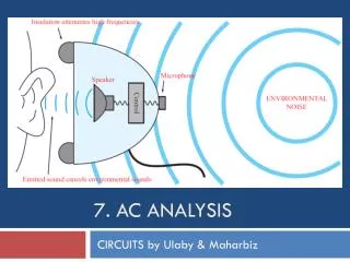
AC characteristics Frequency Response HIGH FREQUENCY MODEL OF OPAMP
AC characteristics Frequency Response OPEN LOOP GAIN VS FREQUENCY
Need for frequency compensation in practical op-amps • Frequency compensation is needed when large bandwidth and lower closed loop gain is desired. • Compensating networks are used to control the phase shift and hence to improve the stability
Frequency compensation methods • Dominant- pole compensation • Pole- zero compensation
Slew Rate • The slew rate is defined as the maximum rate of change of output voltage caused by a step input voltage. • An ideal slew rate is infinite which means that op-amp’s output voltage should change instantaneously in response to input step voltage
UNIT-III Applications of Op Amp
Instrumentation Amplifier In a number of industrial and consumer applications, the measurement of physical quantities is usually done with the help of transducers. The output of transducer has to be amplified So that it can drive the indicator or display system. This function is performed by an instrumentation amplifier
Features of instrumentation amplifier • high gain accuracy • high CMRR • high gain stability with low temperature co- efficient • low dc offset • low output impedance
Differential amplifier This circuit amplifies only the difference between the two inputs. In this circuit there are two resistors labeled R IN Which means that their values are equal. The differential amplifier amplifies the difference of two inputs while the differentiator amplifies the slope of an input
Comparator A comparator is a circuit which compares a signal voltage applied at one input of an op- amp with a known reference voltage at the other input. It is an open loop op - amp with output + Vsat
Applications of comparator • Zero crossing detector • Window detector • Time marker generator • Phase detector
Schmitt trigger Schmitt trigger is a regenerative comparator. It converts sinusoidal input into a square wave output. The output of Schmitt trigger swings between upper and lower threshold voltages, which are the reference voltages of the input waveform