RF Impedance measurements versus simulations
440 likes | 661 Vues
RF Impedance measurements versus simulations. Andrea Mostacci. Università di Roma “La Sapienza”, LNF-INFN. Outline. Basic definitions. Coaxial wire method: motivation and validation. Longitudinal coupling impedance. Transverse coupling impedance. Other applications: trapped modes finding.

RF Impedance measurements versus simulations
E N D
Presentation Transcript
RF Impedance measurements versus simulations Andrea Mostacci Università di Roma “La Sapienza”, LNF-INFN
Outline Basic definitions Coaxial wire method: motivation and validation Longitudinal coupling impedance Transverse coupling impedance Other applications: trapped modes finding Impedance for resonant structures Conclusion
Basic definitions Impedance of most element of the LHC is carefully optimized (measurements and simulations). Impedance data stored in a database to derive the impedance model of the machine and eventually compute instability thresholds. L. Palumbo, V. Vaccaro, M. Zobov, LNF-94/041
Simulation tools Wake potentials YES MAFIA, GDFDL General purpose (3D) codes HFSS, MW studio, … Wake potentials NOT DIRECTLY 2D codes: MAFIA2D, SUPERFISH, OSCAR2D … Impedance dedicated codes (2D): ABCI, …
Basic definitions Coaxial wire method: motivation and validation Longitudinal coupling impedance Transverse coupling impedance Other applications: trapped modes finding Impedance for resonant structures Conclusion
2b 2a r Device Under Test Coaxial wire Field in the DUT with/without wire: a cylindrical waveguide (beam pipe) Ultra-relativistic beam field TEM mode coax waveguide Single wire centered/displaced Two wires
2b 2a r Field in the DUT with/without wire: a cylindrical waveguide (beam pipe) Ultra-relativistic beam field TEM mode coax waveguide TM01 mode in a coax waveguide (above cut-off) Cylindrical guide r/b
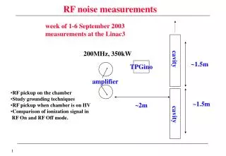
EPA experiment: beam set-up Goal of the experiment: to investigate the transmission properties of a coated ceramic chamber with the CERN EPA electron beam. EPA beam line Titanium coating (1.5 mm) Thickness << skin depth Beam Dump Ref. Chamber DC resistance 1 Ohm Reference chamber (non coated) 500 MeV electron bunch (7e10 particles, s~ 1 ns) Coated Chamber Magnetic field probe EPA 1999: shielding properties EPA 2000: effect of external shields L. Vos et al., AB-Note-2003-002 MD
DUT + wire ns VNA EPA experiment: bench set-up The same ceramic chambers used in the beam experiment have been measured within a coaxial wire set-up, using the same magnetic field probes. VNA with time domain option wire diameter: 0.8 mm Matching resistors: 240 Ohm Synthetic pulse (300 MHz BW) 50 Ohm HF magnetic Field probe Just like in the early days of coaxial wire techniques (Sand and Rees,1974)
Shallow cavity Bench vs beam measurement in EPA Beam/wire axis Vacuum chamber External shield Titanium coating The external shield is electrically connected to the vacuum chamber. Ceramic chamber Field probe
Shallow cavity Bench vs beam measurement in EPA The external shield carries image currents and field penetrates the thin resistive (titanium) layer if this external bypass is present. EPA, 1999
Outline Basic definitions Coaxial wire method: motivation and validation Longitudinal coupling impedance Transverse coupling impedance Other applications: trapped modes finding Impedance for resonant structures Conclusion
Transmission line model DUT + Coaxial Wire = TEM transmission line (with distributed parameters) The DUT coupling impedance is modeled as a series impedance of an ideal REFerence line. Coupling impedance is obtained from the REF and DUT characteristic impedances and propagation constants. Transmission line are characterized via S-parameters with Vector Network Analysers (transmission measurements preferred). In the framework of the transmission line model, the DUT impedance can be computed from S-parameters. Practical approximated formulae Review: F. Caspers in Handbook of Accelerator Physics and Engineering (‘98)
Improved log formula (Vaccaro, 1994) 2b 2a Log formula (Walling et al, 1989) r Hahn-Pedersen formula (1978) Systematic errors are discussed in E. Jensen, PS-RF-Note 2000-001 (2001) H. Hahn, PRST-AB 3 122001 (2001) Coupling impedance formulae Small Impedance wrt to Zc Lumped element: DUT length << l Already implemented in the conversion formula of modern VNA
Theory L=2.31 m Lf=1.66 m MKE kicker measurements Measurement performed in 2000 (CERN-SL-2000-071): 7 cells module. Coupling impedance >> characteristic impedance (300 Ohm) Correction to the improved LOG formula At low frequencies (l ~ L), theory is closer to standard log formula.
A model for the LHC injection kicker RF contacts Improvement of RF match towards HF. PS-RF-Note 2002-156 rectangular steel profile magnet cold conductor Ceramic test chamber with 30 printed conducting strips (different widths) inside, using the same technology of the final LHC kicker. Copper tape surrounding the right end of the ceramic tube in order to make a capacitor between the right port and the strip line (point C). HFSS simulation of the bench measurement H. Tsutsui LHC Project Note 327 (2003) Simplification: 12 strip lines with the same width. Current bypass conductor included.
17.3 MHz 30.8 MHz MHz LHC kicker: meas. and simulations HFSS simulations RF measurement H. Tsutsui, LHC Project Note 327 PS-RF-Note 2002-156 14 MHz 28 MHz Resonance @ 17.3 MHz (700 Ohm) is due to the capacitor and the inductance created by the strip and the outer support. To dump it a ferrite ring was set (agreement between measurement and simulations). Resonance @ 30 MHz is a transverse resonance and it may be related to slightly offset or not properly tightened wire.
442 MHz 846.4 MHz MHz LHC kicker: meas. and simulations HFSS simulations RF measurement H. Tsutsui, LHC Project Note 327 PS-RF-Note 2002-156 410 MHz 810 MHz The 442.3 MHz and 846.4 MHz peaks are due to coaxial waveguide resonance at the copper tape.
RF measurements vs simulation: longitudinal impedance measurements Longitudinal coupling impedance bench measurements are reasonably well understood but not always “easy” and the technique is “well established”. With modern simulation codes, one can derive directly the coupling impedance or simulate the bench set-up with wire, virtually for any structure. Evaluation of coupling impedance from measured or simulated wire method results require the same cautions. Simulations and RF measurements usually agree well. Comparison with numerical results are very useful to drive and to interpret the measurements. Simulation may require simplified DUT model which should reproduce the main DUT electromagnetic features.
Outline Basic definitions Coaxial wire method: motivation and validation Longitudinal coupling impedance Transverse coupling impedance Other applications: trapped modes finding Impedance for resonant structures Conclusion
wire spacing (~10% of the DUT radius) Transverse impedance measurements The transverse impedance is proportional (at a given frequency) to the change of longitudinal impedance due to lateral displacement of the beam in the plane under consideration (H or V): Panowsky-Wentzel theorem. Two parallel wires are stretched across the DUT (odd mode). Panowsky-Wentzel Two wires/loop from improved log formula At low frequency: l>> DUT length Lumped element formula Traditional approach: Nassibian-Sacherer (1977), ...
Single displaced wire or two wires? In the two wires bench set-up only “dipole field components”: no longitudinal electric field components on axis (metallic image plane between wires). Some devices exhibit a strong azimuthal asymmetry in the image current distribution due to variation of the conductivity (e.g. ferrite in kickers) or to the cross section shape. In order to get a more complete view of the transverse kick on the beam, it may be useful to characterize the device with a single wire. H. Tsutsui, SL-Note-2002-034 AP Measuring transverse impedance with a single displaced wire. Panowsky-Wentzel theorem Variation of the longitudinal impedance as a function of displacement for a single wire.
RF measurements vs simulation: transverse impedance measurements Transverse impedance measurement technique are more delicate particularly for asymmetric devices (TW kickers like SPS MKE). New measurement procedures oriented to particular DUTs are being proposed (e.g. SNS kicker measurements, H. Hahn 2004). Numerical simulations are necessary to control measurement procedure. Schematic model of DUT feasible for simulations should not introduce non physical symmetries or approximation.
Outline Basic definitions Coaxial wire method: motivation and validation Longitudinal coupling impedance Transverse coupling impedance Other applications: trapped modes finding Impedance for resonant structures Conclusion
Recombination beam pipe (original, tapered geometry) Trapped modes finding A coaxial wire set-up can be used to study the behavior of a given DUT when passed through by a relativistic beam (e.g. see if trapped mode is excited, beam transfer impedance). MAFIA simulations were showing a small trapped mode in some LHC IR. Real Imag. B. Spataro (INFN-LNF) To understand better, simulations on approximated (rectangular) geometries were carried out and they showed stronger resonance peaks. CERN, LBNL, LNF-INFN collaboration, NIMA 517 (2004)
Measurement feasibility study: HFSS Idea: excite the trapped mode with a coaxial wire in a scaled (simple) rectangular prototype. a= 66 mm b= 18 mm c= 85 mm
“No” impedance Measurement feasibility study: HFSS Idea: excite the trapped mode with a coaxial wire in a scaled (simple) rectangular prototype. a= 66 mm b= 18 mm c= 85 mm 2.5 GHz
Trapped mode “No” impedance Measurement feasibility study: HFSS Idea: excite the trapped mode with a coaxial wire in a scaled (simple) rectangular prototype. a= 66 mm b= 18 mm c= 85 mm 2.5 GHz 2.753 GHz
MAFIA predictions for bench set-up from B. Spataro (INFN-LNF) Beam The wire does not introduce a significant perturbation of this trapped mode, in this case as seen by comparison between HFSS (wire) and MAFIA (no wire).
Measurement set-up and results Tapering the transition, as in the actual geometry strongly reduces the effect of this trapped mode.
Measurement set-up and results Tapering the transition, as in the actual geometry strongly reduces the effect of this trapped mode.
Outline Basic definitions Coaxial wire method: motivation and validation Longitudinal coupling impedance Transverse coupling impedance Other applications: trapped modes finding Impedance for resonant structures Conclusion
Shunt impedance and perturbation measurements Accelerating/deflecting cavities Resonance frequency Quality factor Shunt impedance Wire perturbs longitudinal cavity modes, e.g. lowering the Q and detuning the frequency: coaxial wire set-ups are not recommended for cavity measurements (only special cases, mainly transverse). Bead Pull measurement The field in a cavity can be “sampled” by introducing a perturbing object and measuring the change in resonant frequency. The object must be so small that the field do not vary significantly over its largest linear dimension: it is a perturbation method. Shaped beads are used to enhance perturbation and give directional selectivity
The measurement technique Slater theorem Only longitudinal electric field Form factor can be calculated for ellipsoid or calibrated in known fields (e.g. TM0n0 of a pillbox cavity). The frequency variation can be measured by the variation of the phase at the unperturbed resonant frequency (very precise initial tuning needed!). Transmission measurement It allows visualizing the field shape on the VNA screen
An 11 GHz cavity for SPARC Standing wave accelerating cavity (p mode) 9 cells prototype Correction of linac RF voltage Resonance frequency: 11.424 GHz r = 1.0477 cm (End Cell) r = 1.0477 cm (End Cell) R = 1.0540 cm (Central Cells) Beam axis p = 1.3121 cm t = 0.2 cm Iris radius= 0.4 cm p t End cells radius is reduced (0.6%) to achieve a flat axial field
An 11 GHz cavity for SPARC 9 cells Standing wave cavity (p mode) Correction of linac RF voltage Resonance frequency: 11.424 GHz ~17 cm input waveguide LNF-INFN End cells radius is reduced (0.6%) to achieve a flat axial field
11 GHz cavity: accelerating field z axis (cm)
11 GHz cavity: accelerating field z axis (cm)
11 GHz cavity: accelerating field z axis (cm)
11 GHz cavity: accelerating field z axis (cm) Guide to the expression of uncertainty in measurement (1993).
RF measurements vs simulations: resonant cavities For resonant structure accurate measurements are “easy”, provided understanding of bench set-up details (e.g. glue effect in 11 GHz measurements). Very good agreement between measurement and simulations. Bead pull measurements are used to see if the DUT fits the design specifications and still required for tuning multiple cell cavities. Q measurement on a cavity has precision better than 1%. R/Q is usually done with computer codes, measurements are often only confirmations.
Conclusions The most common methods of measuring coupling impedance: wire method (long. and trans. impedance) and bead pull method (resonant structures). There are several codes usable to estimate coupling impedances (MAFIA, HFSS, GDFDL, MWstudio, ABCI, OSCAR2D, Superfish …). Impedance can be computed by numerical RF simulators or directly or by simulating the wire measurement. Numerical simulations often deal with simplified models: i.e. you must have some insight in the problem. With a reasonable and accurate modeling, a longitudinal impedance simulation usually reproduce experimental results (and viceversa). Transverse impedance requires a much deeper control of both simulations and bench measurements, particularly for some special devices. Impedances of resonant modes are well reproduced by simulation with high reliability.
Acknowledgements I thank F. Ruggiero, B. Spataro and L. Palumbo who gave me the opportunity of giving this talk. F. Caspers (CERN), L. Palumbo (Un. Roma “La Sapienza”), B. Spataro (INFN) and H. Tsutsui (Sumitomo) helped me with fruitful discussions. Most that the work presented here has been done at CERN in SL-AP and PS-RF groups. The EPA experiment was organized and carried out also by L. Vos, D. Brandt and L. Rinolfi (CERN). Also D. Alesini, V. Lollo, A. Bacci, V. Chimenti (INFN) are involved in the design and the prototyping of the 11 GHz cavity for SPARC. Students of our university laboratory substantially helped in setting up the bead-pull measurement for SPARC cavities. Thank you for your attention