FDT Use Cases ( beyond device configuration )
540 likes | 740 Vues
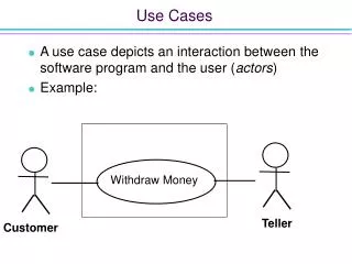
FDT Use Cases ( beyond device configuration ). … uploads and downloads device parameters. ... a Frame Application that …. … opens DTM user interfaces for offline or online parameterization. … has a Tree View on left hand side that shows hierachical ordered network topology.

FDT Use Cases ( beyond device configuration )
E N D
Presentation Transcript
… uploads and downloads device parameters ... a Frame Application that … … opens DTM user interfaces for offline or online parameterization … has a Tree View on left hand side that shows hierachical ordered network topology Motivation for this presentation • FDT is more than…
Scenarios • Data exchange between Frame Applications • Reporting / Documentation • Audit Trail • Alternative Communication Paths • Bus Master Configuration • Control System Configuration • Bus Master without Gateway capabilities • Process Monitoring • Network Management • Update and Replacement
Data exchange between Frame Applications • Scenario • Data exchange between different Frame Applicationse.g. Data exchange between a stand-alone Service Tool and a Control System • FDT Definition • Definition of standard topology dataexchange format • Frame Application generates or reads XML files according FDTTopologyImportExportSchema • FDTTopologyImportExportSchema defines Exchange of topology information Exchange of DTM/BTM and device/block type information Exchange of DTM/BTM instance data (Stream or PropertyBag)
CommunicationDTM GatewayDTM GatewayDTM DeviceDTM DeviceDTM Data exchange between Frame Applications Example XML
3. Check-out single device data set or sub-network from database and export to XML file 7. Synchronize single device data set or sub-network with data in XML file and check-in to database Data Sharing XML File 4. Import data from XML file 6. Export data to XML file 1. Load data from database 2. Parameterization via device specific DTM Vendor A: System Engineering Tool 5. Maintenance via device specific DTM Both Frame Applications use same DTM type and load it with shared device data Data exchange between Frame ApplicationsExample: System Engineering Tool Service Tool
3. Check-out single device data set or sub-network from database and export to XML file 7. Synchronize single device data set or sub-network with data in XML file and check-in to database Data Sharing XML File 4. Import data from XML file 6. Export data to XML file 1. Load data from database 2. Parameterization via device specific DTM Vendor C: Pocket Tool Vendor A: System Engineering Tool 5. Maintenance via device specific DTM Frame Applications use different, but compatible DTM types and load it with shared device data Data exchange between Frame ApplicationsExample: System Engineering Tool PDA
Scenarios • Data exchange between Frame Applications • Reporting / Documentation • Audit Trail • Alternative Communication Paths • Bus Master Configuration • Control System Configuration • Bus Master without Gateway capabilities • Process Monitoring • Network Management • Update and Replacement
Reporting & Documentation • Scenario • Generation of device configuration & parameterization reports • Print out of reports • FDT Definition • DTM interface (IDtmDocumentation) called to request report information for specific data (e.g. device configuration, offline or online configuration etc.) • Definition of documentation data format - DTMDocumenationSchema.xml • Data transformation to HTML reports
IDtmDocumentation:GetDocumentation() Reporting & DocumentationExample: Print of Device Settings (Frame Application Style) DTM
IDtmDocumentation:GetDocumentation() Reporting & DocumentationExample: Print of Device Settings (DTM Style) DTM
Scenarios • Data exchange between Frame Applications • Reporting / Documentation • Audit Trail • Alternative Communication Paths • Bus Master Configuration • Control System Configuration • Bus Master without Gateway capabilities • Process Monitoring • Network Management • Update and Replacement
Audit Trail • Scenario • Record data changes (what has been changed by who) Example: - Device parameter XYZ changed from 0815 to 4711 by user Operator - Function Device Reset executed by user Operater at 10.30pm - 2004-02-04 - … • Change history documentation • FDT Definition • Frame Application interface IDtmAuditTrailEvents that is called by DTM whenever • Device Parameter is changed • Device Status changes • Device related operation is executed
Save Frame Application Change Some Parameters Get DTM Data IDtmAuditTrailEvents:OnAuditTrailEvent() Audit TrailExample: Change History Recording
Scenarios • Data exchange between Frame Applications • Reporting / Documentation • Audit Trail • Alternative Communication Paths • Bus Master Configuration • Control System Configuration • Bus Master without Gateway capabilities • Process Monitoring • Network Management • Update and Replacement
Alternative Communication Paths • Scenario • Device has multiple physical communication interfaces • field bus network (e.g. Profibus, FF, Modbus etc.) • vendor specific service interface (e.g. RS 232, IrDA, Bluetooth etc) • User wants to select path to use • FDT Definition • Device DTM supports multiple protocols • DTM Information XML contains multiple „required“ protocols • Device DTM is assigned to muliple Communication or Gateway DTMs
DTM 3 DTM 1 DTM 2 SetCommunication (null) SetCommunication (DTM 1) SetCommunication (DTM 3) ReleaseCommunication () SetCommunication(DTM 2) DTM 4 Alternative Communication Paths
Scenarios • Data exchange between Frame Applications • Reporting / Documentation • Audit Trail • Alternative Communication Paths • Bus Master Configuration • Control System Configuration • Bus Master without Gateway capabilities • Process Monitoring • Network Management • Update and Replacement
Bus Master Configuration • Scenario • Configuration of communication master • Setup of cyclic communication • FDT Definition • Master Configuration Data in DTM Parameter for a slave device XML according DTMParameterSchema) e.g. for Profibus: BusMasterConfigurationPart + GSD information
Functionality is typically realized by a PLC specific Bus Master Configuration Tool. Configure Bus Master and setup cyclic communication PLC DTM DTM representing PLC Bus Master (Module) DTM DTM representing Bus Master Module plugged into PLC IDtmParameter:GetParameter() Read GSD and BusMasterConfigurationPart from Parameter XML Slave DTM 1 Slave DTM 2 Slave DTM 3 GSD + BusMasterConfigPart GSD + BusMasterConfigPart GSD + BusMasterConfigPart Bus Master ConfigurationExample: Profibus Master Configuration
Scenarios • Data exchange between Frame Applications • Reporting / Documentation • Audit Trail • Alternative Communication Paths • Bus Master Configuration • Control System Configuration • Bus Master without Gateway capabilities • Process Monitoring • Network Management • Update and Replacement
Control System Configuration • Scenario • Devices connected to a field bus must be made known to the control system • Device input and output signals must be create and integrated into functional control system planning - e.g. mapping of device input / output to PLC variables • FDT Definition • DTM (Process) Channels • IFdtChannel interface • Channel Parameter XMLs according protocol specific FDT Annex Schema
Process Channel Parameter typically contain following process variable information: - Name, Tag, ID - Data type - Singnal type (input / output) - Information type (Semantic ID) - Address information (e.g. position / length) - Flag indicating that it is in use by control system (protectedByChannelAssignment) PLC DTM Bus Master (Module) DTM Process Channels describe variables exchanged between the device and the PLC Cyclic data exchange Process Var 1 Process Var 2 Process Var 3 Process Ch 3 Process Ch 2 Process Ch 1 IFdtChannel:GetParameters() IFdtChannel:GetParameters() Control System ConfigurationRole of Process Channels Device DTM
Functionalitiy is typically realized by a Control System specific Programming Suite. Symbolic variable names are used for Control System programming PLC DTM Symbolic names are applied to variables Bus Master (Module) DTM Process Channel information is mapped to PLC Module variables Process Ch 3 Process Ch 2 Process Ch 1 Control System ConfigurationProcess Channel Variable Mapping Device DTM
PLC DTM Program is downloaded to PLC Bus Master module maps process values into PLC variables in memory.The PLC variables are used in program running in the PLC to control the system. PLC program Process Var 1 Process Var 2 Process Var 3 Cyclic data exchange Control System ConfigurationPLC Program Download
Scenarios • Data exchange between Frame Applications • Reporting / Documentation • Audit Trail • Alternative Communication Paths • Bus Master Configuration • Control System Configuration • Bus Master without Gateway capabilities • Process Monitoring • Network Management • Update and Replacement
Master DTM Device DTM Bus Master without Gateway capabilities • Scenario • Bus Master in a PLC doesn’t have Gateway capabilities • Device DTMs can’t connect to its device through PLC • FDT Definition • Nothing special! Master DTM only supports services to access cyclic data (e.g. Profibus DPVO) Device DTM needs acyclic services (e.g. Profibus DPV1) for configuration & parameterization
Parallel Profibus Class 2 Master Configure Bus Master and setup cyclic communication Master DTM Communication DTM Cyclic services are used for observation Read GSD + BusMasterConfigurationPart Acyclic services are used for configuration & parameterization Cyclic data exchange Device DTM Bus Master without Gateway capabilitiesExample: PLC with Profibus Master Module
Scenarios • Data exchange between Frame Applications • Reporting / Documentation • Audit Trail • Alternative Communication Paths • Bus Master Configuration • Control System Configuration • Bus Master without Gateway capabilities • Process Monitoring • Network Management • Update and Replacement
Process Monitoring • Scenarios • Process Visualization • Condition Monitoring - Device status • Gathering of asset management related information • Health / predictive maintenance information • Operation counters • etc. • FDT Definition • DTM (Process) Channels • IFdtChannel interfaceChannel Parameter • XMLs according protocol specific FDT Annex Schema • Single Device Data Access • IDtmSingleDeviceDataAccess interface • Data XML according DTM Item Schema (protocol independent) • Semantic IDs
Process Channel Parameter contain information how to request process variables directly from the device, e.g. via Profibus DPV1 Comm DTM Process Channel Parameter can also contain information about alarms and ranges Process Channels describe variables that are exchanged via parallel (acyclic) communication path Process Var 4 Process Var 5 Process Var 6 Device DTM Process Ch 6 Process Ch 5 Process Ch 4 IFdtChannel:GetParameters() Process MonitoringRole of Process Channels
Process Monitoring Frame Application uses Communication or Gateway DTM communication interface to directly connect to devices and read process variables. Comm DTM IFdtCommunication: TransactionRequest() Process Var 4 Process variable value read from the device. Returned byte stream must be converted to data type described in Process Channel Parameter Process variable address information from Process Channel Parameter Process MonitoringProcess Value Reading
If OPC Server acts as a FDT Frame Application it even can use the Communication or Gateway DTMs, so it becomes independent from used hardware. OPC Server Configuration interface Comm DTM Frame Application reads Process Channel Parameters and feeds OPC Server with information Process Monitoring Application uses protocol independent OPC interface to read process variables Process Var 4 Process Var 5 Process Var 6 Device DTM Process Ch 6 Process Ch 5 Process Ch 4 IFdtChannel:GetParameters() Process MonitoringProcess Value Reading via OPC Server (1/2) OPC Server
Process MonitoringDrawback of Process Channel • Information is protocol dependent • XML Schemas defined by FDT Protocol Annex • Frame Application must be prepared for every protocol Mechnismus doesn’t work for new introduced or vendor specific protocols! • Solution: Single Device Data Access interface • Provides protocol independent way to access process variables
Comm DTM Process Var 4 Process Var 5 Process Var 6 Device DTM IDtmSingleDeviceData::GetItemLisl IDtmSingleDeviceDataAccess:Read() Process Ch 6 Process Ch 5 Process Ch 4 GetItemList() and DTM Process Channels may contain redundant information. Both describing the process variables. Process MonitoringRole of Single Device Data Access interface
Comm DTM OPC Server starts Device DTM and uses Single Device Data Access interface if protocol is unknown or no Process Channel is provided for the process variable. Process Var 4 Process Var 5 Process Var 6 Device DTM Process MonitoringProcess Value Reading via OPC Server (2/2) OPC Server
Process MonitoringDrawback of Single Device Data Access Interface • All Device DTMs must be started / shut-downed • Start / shutdown of DTM is time consuming • DTMs take much memory Lower performance than Process Channel mechanism
Scenarios • Data exchange between Frame Applications • Reporting / Documentation • Audit Trail • Alternative Communication Paths • Bus Master Configuration • Control System Configuration • Bus Master without Gateway capabilities • Process Monitoring • Network Management • Update and Replacement
Network Management • Scenarios • Automatic creation of network topology • Verification if manual engineered network topology maps to field bus network • Address Management • FDT Definition • DTM information about supported hardware • XML according FDT<protocol>DeviceTypeIdentSchema • IDtmInformation2 interface to request information • Scan of field bus and information about connected devices • XML according FDT<protocol>ScanIdentSchema • IFdtChannelScan:ScanRequest to perform scanning • Address setting mechanism - IFdtChannelSubTopology2 to trigger address setting
Start all found DTMs and request DTM and hardware information (IDtmInformation / IDtmInformation2) Scan Windows-Registry for installed DTMs DTM Store information regarding DTM Store information regarding DTM Device Types Drivers representing the devices in the software Store protocol information Store information regarding hardware (pyhsical devices) which are supported by the DTM Device Types. Network ManagementDTM / Device Catalog FDT-Category FDT_DTM MMDTM.ExampleDevices … … … XYDTM.XYZDevices Windows-Registry
CommDTM Scan field bus Bus Address 1Manufacturer ID = 1234Device ID = 1Hardware Vers = 2.3.1.2Software Vers = 3.12.4 IFdtChannelScan::ScanRequest(protocolId); IDtmScanEvents::OnScanResponse() Bus Address 3Manufacturer ID = 1234Device ID = 2Hardware Vers = 2.4.1.2Software Vers = 3.00.4 Search for corresponding entry in Hardware Info Table Manufacturer ID = 1234Device ID = 1Hardware Vers = 2.3.1.2Software Vers = 3.12.4 Manufacturer ID = 1234Device ID = 2Hardware Vers = 2.4.1.2Software Vers = 3.00.4 Network ManagementScan Field Bus and Create Network Topology (1/2) Bus Address = 1 Bus Address = 3
Trigger bus address setting at Communication DTM for the newly added Device DTMs CommDTM Bus Address 1Manufacturer ID = 1234Device ID = 1Hardware Vers = 2.3.1.2Software Vers = 3.12.4 IDtmScanEvents::OnScanResponse() IFdtChannelSubTopology2: SetChildrenAddresses() Set bus addresses in DTM Parameter XML Bus Address 3Manufacturer ID = 1234Device ID = 2Hardware Vers = 2.4.1.2Software Vers = 3.00.4 Manufacturer ID = 1234Device ID = 1Hardware Vers = 2.3.1.2Software Vers = 3.12.4 Manufacturer ID = 1234Device ID = 2Hardware Vers = 2.4.1.2Software Vers = 3.00.4 Device DTM Device DTM Network ManagementScan Field Bus and Create Network Topology (2/2) Bus Address = 1 Bus Adress = 3
Trigger bus addresssetting to change addressin Comm DTM ActiveX control CommDTM Open ActiveX control IFdtChannelSubTopology2:SetBusAddresses(withGUI) Set bus addresses in DTM Parameter XML Manufacturer ID = 1234Device ID = 1Hardware Vers = 2.3.1.2Software Vers = 3.12.4 Manufacturer ID = 1234Device ID = 2Hardware Vers = 2.4.1.2Software Vers = 3.00.4 Device DTM Device DTM Network ManagementBus Address Management in User Interface Bus Address = 1 Bus Address = 3
Scenarios • Data exchange between Frame Applications • Reporting / Documentation • Audit Trail • Alternative Communication Paths • Bus Master Configuration • Control System Configuration • Bus Master without Gateway capabilities • Process Monitoring • Network Management • Update and Replacement
Update & Replacement • Scenarios • Device is replaced by another instance of the same type • Device is replaced by another device of the same classification, but from another manufacturer • FDT Definition • Dataset Format IDs • DTM Parameter access • DTM Parameter XML (IDtmParameter interface) • DTM Item XML (IDtmSingleInstanceDataAccess interface) • Semantic IDs
Update & ReplacementScenario: Update (1/4) • Device is replaced by another instance of the same type • New instance has new firmware version that is not supported by the installed DTM • DTM must be upgraded • New DTM uses different data set format, but can load old data set format
1. Save 2. DTM stores binary data in Frame Application database + binary data format information (used and supported) Vendor specific identifier that specifies format of DTM data set. Old DTM Update & ReplacementScenario: Update (2/4)
5. Update DTM / Device Catalog and store information about new installed DTM (IDtmInformation / IDtmInformation2) Scan Windows-Registry for installed DTMs 4. Install new DTM and register in Windows-Registry DTM Store dataset formats that are supported FDT-Category FDT_DTM MMDTM.ExampleDevices … … … XYDTM.XYZDevices Windows-Registry Update & ReplacementScenario: Update (3/4) 3. Replace old device with new device
7. New installed DTM loads „old“ dataset and converts it to new format Frame Application uses dataset format stored together with DTM binary data to search for DTM supporting this format New installed DTM Update & ReplacementScenario: Update (4/4)
Update & ReplacementScenario: Replacement (1/2) • Device is replaced by another device of the same classification, but from another manufacturer • DTM must be replaced by another DTM • Data set is incompatible • Data exchange between two totally different DTM provided by different vendors