Download
1 / 33
330 likes | 507 Vues
A Project on Development of a GUI widget For MACE Telescope using Qt4. & Implementation of FAT using C++ prepared by Mayank Mohta 2006A7PS050 Dushyant Arora 2006A7PS083. PROJECT - 1. Development of a GUI widget for MACE Telescope using Qt4. About the MACE Telescope.

E N D
A Project on Development of a GUI widget For MACE Telescope using Qt4. & Implementation of FAT using C++ prepared by Mayank Mohta 2006A7PS050 Dushyant Arora 2006A7PS083
PROJECT - 1 Development of a GUI widget for MACE Telescope using Qt4
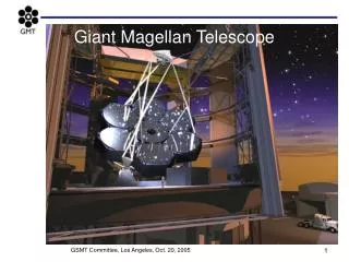
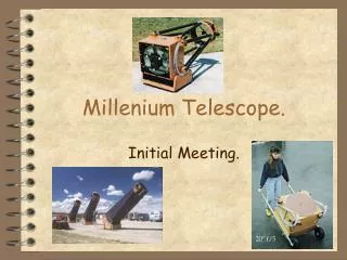
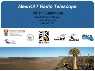
About the MACE Telescope • Location : Hanle , Leh, India. • Altitude: 4500 m asl. • Size: 21 m telescope. • Resolution: 960 Pixel Camera. • 1408 PMTs. • Energy Range : 30 GeV – 30 TeV.
Requirements on the CDACS • Sampling PMT signals • Recognizing of cosmic event of interest from the PMT signals • Generating of trigger • Digitizing PMT signal profile • Collecting the data to a central location • Applying further data reduction criterion • Downloading to a ground station • Setting and Monitoring of HV and anode current • Monitoring temperature and heating
About Qt • Qt is a comprehensive C++ framework for developing cross-platform GUI applications using a "write once, compile anywhere" approach. • Developed by Haavard Nord and Eirik Chambe-Eng and Qt 1.0 released on May 1995. • The company was incorporated on March 4, 1994, originally as Quasar Technologies, then as Trolltech • Both Open Source and licensed versions available. • A Cross-platform, graphical, application development toolkit that enables you to compile and run your applications on Windows, Mac OS X, Linux, and different brands of Unix. • Qt4 has about 500 classes and more than 9000 functions. • In addition to Qt's hundreds of classes, there are add-ons that extend Qt's scope and power like Qt Script for Applications (QSA) and the Qt Solutions
About Qt • Easy-to-use template containers, advanced model/view functionality, a fast and flexible 2D painting framework, and powerful Unicode text viewing and editing classes are few improvement in Qt4. • Qt Designer allows you to design and build widgets(a visual element in a user interface) and dialogs using on-screen forms using the same widgets that will be used in your application. Applications Build using Qt Qt is the foundation on which the K Desktop Environment (KDE) and the many exciting applications like Opera web browser, Adobe Photoshop Album, Skype, Google Earth etc. have been built using Qt.
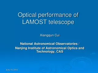
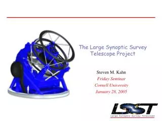
Operational Features Required by the Widget • · There are 1408 Photo Multiplier Tubes (PMT) in the telescope, each PMT in a unique group of 16 . Depending on the intensity of light falling on each tube a voltage is generated and using ADC it is converted into a float value. These values will be available to us in a 2-dimensional array (Assume the array to be PMT_values[][]. • · The user can make various intervals and assign a colour value to each interval. • · Using the float values available in the array and the intervals made the widget should generate a pixmap colouring the cell[i][j] with the colour corresponding to interval in which PMT_values[i][j] lies. • The widget should also display the zoomed image of the group of 16 cells on which the user clicks.
Stage 1 Stage 2
Stage 3 Model 1 Model 2
Integrating the widget with Qt designer • After creating the widget with the necessary requirements, our next task was to integrate the widget with the Qt designer so that it could be directly used in other projects • The plugin approach requires the creation of a plugin library that Qt Designer can load at run-time and use to create instances of the widget
FUTURE ASPECTS • The data acquisition presently is merely a simulation using random function. Integrating it with the database and acquiring data from database in real time is also a big challenge. • Feature of zoom on scrolling can be added for better analysis. • The number of intervals (5 or less). Provision can be provided to change this number at runtime. • Stringent efficiency measurements and rigorous testing needs to be done before it can be actually used in the telescope console.
Implementation of FAT (File Allocation Table) Using C++ An ECG data acquisition and recording system has been developed at B.A.R.C. This system will record the patients ECG data and store it on an embedded device. This embedded device will store this data on a SD card or a USB Flash Drive so that it can be viewed for analysis in the future. The doctors can simply plug the USB Drive/SD Card to a computer and view the patients ECG data. Our project was to develop a small module for the embedded device. The data received from the patient is in raw form and needs to be stored in an organized and systematic fashion onto to the storing media. We have implemented the FAT format and disk organization norms for the same.
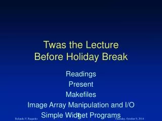
Byte Offset (in hex) Field Length Sample Value Meaning 00 3 bytes EB 3C 90 Jump instruction 03 8 bytes MSDOS5.0 OEM Name in text 0B 25 bytes BIOS Parameter Block 24 26 bytes Extended BIOS Parameter Block 3E 448 bytes Bootstrap code 1FE 2 bytes 0x55AA End of sector marker
The Bios Parameter Block contains information about the disk. Bytes per Sector, Sectors per Cluster, Reserved Sectors, No. of FATs, Total sectors in the logical volume, Sectors per FAT, Sectors per track, etc.
Value Meaning 00H Directory entry has never been used; end of occupied portion of directory 05H First Character of Filename is actually E5H 2EH Entry is an alias for the current or the parent directory. If the next byte is also 2EH, the cluster field contains the cluster number of the parent directory (zero if the parent directory is the root directory). E5H File has been erased. Root Directory The root directory contains 32-byte entries that describe files, other directories, and the optional volume label Interpretation of the first byte of a directory entry
Filename (8 bytes) Extension (3 bytes) File Attribute (1 byte) Reserved (10 bytes) Time created or last updated (2 bytes) Date created or last updated (2 bytes) Starting Cluster (2 bytes) File Size (4 bytes) Format of a single entry in a disk directory. Total length is 32 bytes (20H bytes)
Value Meaning (0)000H Cluster Available (F)FF0 – (F)FF6H Reserved Cluster (F)FF7H Bad Cluster (F)FF8 – (F)FFFH Last Cluster of a File (X)XXX Next Cluster of the File File Allocation Table (FAT) Table that links the files having multiple clusters by storing which is the next cluster of the file.
The Files Area • The remainder of the volume after the root directory is known as the files area. MS-DOS views the sectors in this area as a pool of clusters, each containing one or more logical sectors, depending on the disk format. • Each cluster has a corresponding entry in the FAT that describes its current use: available, reserved, assigned to a file, or unusable (because of defects in the medium • Because the first two fields of the FAT are reserved, the first cluster in the files area is assigned the number 2.
Our Program We assume that we have a disk image (raw hex dump) of a mass storage device in an array (DiskImage). This Disk Image is the copy of the raw data physically present on the Storage device (like a floppy /SD card/ USB flash drive etc.). All the functions manipulate the array DiskImage. We have created a menu allowing the user to perform various actions on the DiskImage array.
Future Aspects • There are several improvements and additions that can be made to our project, which we were not able to accomplish due to lack of time. They are as follows: • Currently the options are menu based. It will be much more user friendly if it is command based. • The user can write and append files but cannot edit them. • Presently, the write function takes input from users and stores it in text format. An extension can be made to write binary files. • Efficiency measurements and rigorous testing needs to be done before it can be actually used in embedded systems.