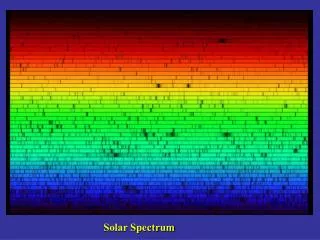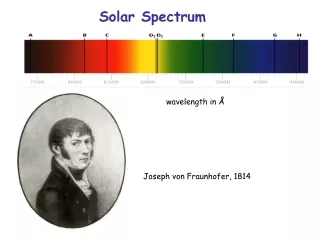
Solar Spectrum
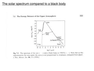
This article provides a comprehensive overview of the solar spectrum, detailing black body radiation emitted by light bulbs at 3000°K and the sun's surface at 6000°K. It discusses the atmospheric absorption and scattering processes affecting solar radiation as it passes through air masses, noting significant losses due to Rayleigh scattering and cloud cover. Furthermore, it outlines the importance of direct and diffuse radiation components and introduces methods for calculating solar insolation levels, peak sunlight hours, and the impact of tilt angles on solar energy harvesting.

Solar Spectrum
E N D
Presentation Transcript
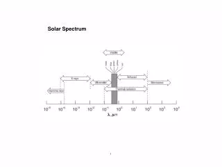
Solar Spectrum -Black body radiation Light bulb 3000°K Red->Yellow->White Surface of Sun 6000°K
Solar Spectrum -Black body radiation Light bulb 3000°K Red->Yellow->White Surface of Sun 6000°K
Solar Spectrum -Black body radiation Light bulb 3000°K Red->Yellow->White Surface of Sun 6000°K
Solar Spectrum -Atmospheric Absorption and Scattering Light bulb 3000°K Red->Yellow->White Surface of Sun 6000°K
Solar Spectrum -Atmospheric Absorption and Scattering Light bulb 3000°K Red->Yellow->White Surface of Sun 6000°K
Solar Spectrum -Atmospheric Absorption and Scattering Air Mass through which solar radiation passes
Solar Spectrum -Atmospheric Absorption and Scattering Air Mass through which solar radiation passes
30% lost to Rayleigh Scattering λ-4 (blue sky/orange sunset) Scattering by aerosols (Smoke, Dust and Haze S.K. Friedlander) Absorption: Ozone all below 0.3 µm, CO2, O2, H2O
10% added to AM1 for clear skies by diffuse component Increases with cloud cover ½ lost to clouds is recovered in diffuse radiation
Appendix A1 Direct and Diffuse Radiation Global Radiation = Direct + Diffuse Radiation AM1.5 Global AM1.5G irradiance for equator facing 37° tilted surface on earth (app. A1) Integral over all wavelengths is 970 W/m2 (or 1000 W/m2 for normalized spectrum) is a standard to rate PV Close to maximum power received at the earths surface.
Standard Spectrum is compared to Actual Spectrum for a site Solar Insolation Levels March September June December
Cape Town/Melbourne/Chattanooga Gibraltar/Beirut/Shanghai
Need: -Global radiation on a horizontal surface -Horizontal direct and diffuse components of global value -Estimate for tilted plane value Equations given in Chapter on Sunlight Peak sun hours reduces a days variation to a fixed number of peak hours for calculations SSH = Sunshine Hours Total number of hours above 210 W/m2 for a month Equations in Chapter 1 to convert SSH to a useful form.
Estimates of Diffuse Component Clearness Index KT = diffuse/total This is calculaed following the algorithm given in the chapter Use number of sunny and cloudy days to calculate diffuse and direct insolation Described in the book
Tilted Surfaces PV is mounted at a fixed tilt angle
Calculation for Optimal Tilt Angle Given in the Chapter
Market Share CIS= Copper Indium Gallium Selenide a-Si= Amorphous Silicon Ribbon= Multicrystalline Silicon from Molten Bath CdTe= Cadium Telluride/Cadmium Sulfide Mono = Monocrystalline Silicaon Multi= Muticrystalline Silicon
http://www.asdn.net/asdn/physics/p-n-junctions.shtml Negative ion cores Depleted of Free Carriers Positive ion cores
On average a minority carrier Travels the diffusion length Before recombining This is the diffusion current Carriers in the depletion region Are carried by the electric field This is the drift current In equilibrium drift = diffusion Net current = 0 Carrier Generation Carrier Recombination Carrier Diffusion Carrier Drift in Depletion Region due to inherent field
I–V characteristics of a p–n junction diode (not to scale—the current in the reverse region is magnified compared to the forward region, resulting in the apparent slope discontinuity at the origin; the actual I–V curve is smooth across the origin). http://en.wikipedia.org/wiki/Diode
I–V characteristics of a p–n junction diode (not to scale—the current in the reverse region is magnified compared to the forward region, resulting in the apparent slope discontinuity at the origin; the actual I–V curve is smooth across the origin). http://en.wikipedia.org/wiki/Diode
Electron-hole pair -Generation -Recombination Carrier lifetime (1 µs) Carrier diffusion length (100-300 µm)