Download

1 / 149
1.65k likes | 2.29k Vues
Chapter 15 Completion of the Design of a Power Transmission. The big picture 15-1 Objectives of this chapter 15-2 Description of the power transmission to be designed 15-3 Design alternatives and selection of the design approach 15-4 Design alternatives for the gear-type reducer

E N D
The big picture • 15-1 Objectives of this chapter • 15-2 Description of the power transmission to be designed • 15-3 Design alternatives and selection of the design approach • 15-4 Design alternatives for the gear-type reducer • 15-5 General layout and design details of the reducer • 15-6 Final design details for the shafts • 15-7 Assembly drawing
The big picture Now we bring together the concepts and design procedures from the last eight chapters to complete the design of the power transmission. Discover Consider how all of the machine elements that you have studied in chapters 7-14 fit together. Think also about the entire life cycle of the transmission, from its design to its disposal.
This chapter presents a summary of the steps that you should take to complete the design. Some procedures are quite detailed. You should be able to apply this experience to any design you are responsible for in the future.
This is where all of the work of Part II of this book comes together. In Chapters 7-14, you learned important concepts and design procedures for many kinds of machine elements that could all be part of a given power transmission. In each case, we mentioned how the elements need to work together.
Now we show the approach to completing the design of a power transmission which demonstrates an integrated approach and illustrates the title of this book, Machine Elements in Mechanical Design. The emphasis is on the whole design. The lesson of this chapter is that you as a designer must constantly keep in mind how the part you are currently working on fits with other parts and how its design can affect the design of other parts.
You must also consider how the part is to be manufactured, how it may be serviced and repaired as necessary, and how it will eventually be taken out of service. What will happen to the materials in the product when they have served their useful life as part of your current project? Although we are using a power transmission in this example, the skills and insights that you will acquire should be transferable to the design of almost any other mechanical device or system.
15-1 OBJECTIVES OF THIS CHAPTER After completing this chapter, you will be able to: 1. Bring together the individual components of a mechanical, gear-type power transmission into a unified, complete system. 2. Resolve the interface questions where two components fit together.
3. Establish reasonable tolerances and limit dimensions on key dimensions of components, especially where assembly and operation of the components are critical. 4. Verify that the final design is safe and suitable for its intended purpose. 5. Add details to some of the components that were not considered in earlier analyses.
15-2 DESCRIPTION OF THE POWER TRANSMISSION TO BE DESIGNED The project to be completed in this chapter is the design of a single-reduction speed reducer that uses spur gears. We will use the data from Example Problem 9-1 in which the gears for the drive for an industrial saw were designed. You should review that problem now and note that it was carried forward through Example Problems 9-1 through 9-4. It was considered again in Section 9-15 where we refined the design using the spreadsheet developed in Section 9-14.
We will also use elements of the mechanical design process that were first outlined in Chapter 1 in Sections 1-4 through 1-6. We will state the functions and design requirements for the power transmission, establish a set of criteria for evaluating design decisions, and implement the design tasks that were outlined in Section 1-6. References 4, 7, and 8 provide additional approaches that you may find useful for other design projects.
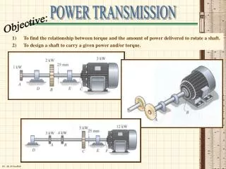
Basic Statement of the Problem We will design a power transmission for an industrial saw that will be used to cut tubing for vehicle exhaust pipes to length prior to the forming processes.The saw will receive 25 hp from the shaft of an electric motor rotating at 1750 rpm. The drive shaft for the saw should rotate at approximately 500 rpm.
Functions, Design Requirements, and Selection Criteria for the Power Transmission Functions. The functions of the power transmission areas follows: 1. To receive power from an electric motor through a rotating shaft. 2. To transmit the power through machine elements that reduce the rotational speed to a desired value.
3. To deliver the power at the lower speed to an output shaft which ultimately drives the saw. Design Requirements. Additional information is presented here for the specific case of the industrial saw. You would normally be responsible for acquiring the necessary information and for making design decisions at this point in the design process.
You would be involved in the design of the saw and would be able to discuss its desirable features with colleagues in marketing, sales, manufacturing planning, and production management and field service, and, perhaps, with customers. The kinds of information that you should seek are illustrated in the following list:
1. The reducer must transmit 25 hp. 2. The input is from an electric motor whose shaft rotates at a full-load speed of 1750 rpm. It has been proposed to use a NEMA frame 284T motor having a shaft diameter of 1.875 in and a keyway to accommodate a 1/2 1/2 in key. See Chapter 21, Figure 21-18 and Table 21-3, for more data on the dimensions of the motor.
3. The output of the reducer delivers power to the saw through a shaft that rotates between 495 and 505 rpm. The speed reduction ratio should then be in the range of 3.46 to 3.53. 4. A mechanical efficiency of greater than 95%is desirable. 5. The minimum torque delivered to the saw should be 2 950 lbin.
6. The saw is a band saw. The cutting operation is generally smooth, but moderate shock may be encountered as the saw blade engages the tubes and if there is any binding of the blade in the cut. 7. The speed reducer will be mounted on a rigid plate that is part of the base of the saw. The means of mounting the reducer should be specified.
8. It has been decided that flexible couplings may be used to connect the motor shaft to the input shaft of the reducer and to connect the output shaft directly to the shaft of the main drive wheel for the band saw. The design for the shaft for the band-saw drive has not yet been completed. It is likely that its diameter will be the same as that of the output shaft of the reducer. 9. Whereas a small, compact size for the reducer is desirable, space in the machine base should be able to accommodate most reasonable designs.
10. The saw is expected to operate 16 hours per day, 5 days per week, with a design life of 5 years. This is approximately 20 000 hours of operation. 11. The machine base will be enclosed and will prevent any casual contact with the reducer. However, the functional components of the reducer should be enclosed in their own rigid housing to protect them from contaminants and to provide for the safety of those who work with the equipment.
12. The saw will operate in a factory environment and should be capable of operation in the temperature range of 50F to 100 F. 13. The saw is expected to be produced in quantities of 5 000 units per year. 14. A moderate cost is critical to the marketing success of the saw.
Selection Criteria. The list of criteria should be produced by an interdisciplinary team composed of people having broad experience with the market for and use of such equipment. The details will vary according to the specific design. As an illustration of the process, the following criteria are suggested for the present design:
1. Safety: The speed reducer should operate safely and provide a safe environment for people near the machine. 2. Cost: Low cost is desirable so that the saw appeals to a large set of customers. 3. Small size. 4. High reliability. 5. Low maintenance. 6. Smooth operation; low noise; low vibration.
15-3 DESIGN ALTERNATIVES AND SELECTION OF THE DESIGN APPROACH There are many ways that the speed reduction for the saw can be accomplished. Figure 15-1 shows four possibilities:(a) belt drive, (b) chain drive, (c) gear-type drive connected through flexible couplings, and (d) gear-type drive with a belt drive on the input side and connected to the saw with a flexible coupling.
Selection of the Basic Design Approach Table 15-1 shows an example of the rating that could be done to select the type of design to be produced for the speed reducer for the saw. A 10-point scale is used, with 10 being the highest rating. Of course, with more information about the actual application, a different design approach could be selected. Also, it may be desirable to proceed with more than one design to determine more of the details, thus allowing a more rational decision.
A modification of the design decision matrix calls for weighting factors to be assigned to each criterion to reflect its relative importance. See References 3 and 7 for extensive discussions of rational decision analysis techniques.
On the basis of this decision analysis, let's proceed with (c), the design of a gear-type speed reducer using flexible couplings to connect with the drive motor and the driven shaft of the saw. It is considered to have a higher level of safety for operators and maintenance people because its rotating components are enclosed. The input and output shafts and the couplings can be covered at the time of installation.
Reliability is expected to be higher because precision metallic parts are used and the drive is enclosed in a sealed housing. The flexing of belts and the significant number of moving parts in a chain drive are judged to provide lower reliability. Initial cost may be higher than for belt or chain drives. However, it is expected that maintenance will be somewhat less, leading to lower cost overall. The space taken by the design should be small, simplifying the design of other parts of the saw.
Design alternative (d) is attractive if there is some interest in providing a variable speed operation in the future. By using different belt drive ratios, we can achieve different cutting speeds for the saw. A further alternative would be to consider a variable-speed electric drive motor, either to replace the need for a reducer at all or to be used in conjunction with the gear-type reducer.
15-4 DESIGN ALTERNATIVES FOR THE GEARTPYE REDUCER Now that we have selected the gear-type reducer, we need to decide which type to use. Here are some alternatives: 1. Single-reduction spur gears: The nominal ratio of 3.50:1 is reasonable for a single pair of gears. Spur gears produce only radial loads which simplify selection of the bearings that support the shafts. Efficiency should be greater than 95% with reasonable precision of the gears, bearings, and seals.
Spur gears are relatively inexpensive to produce. Shafts would be parallel and should be fairly easy to align with the motor and the drive shaft for the saw. 2. Single-reduction helical gears: These gears are equally practical as spur gears. Shaft alignment is similar. A smaller size should be possible because of the greater capacity of helical gears. However, axial thrust loads would be created which must be accommodated by the bearings and the housing. Cost is likely to be somewhat higher.
3. Bevel gears: These gears produce a right-angle drive which may be desirable, but not necessary in the present design. They are also somewhat more difficult to design and assemble to achieve adequate precision. 4. Worm and wormgear drive: This drive also produces a right-angle drive. It is typically used to achieve a higher reduction ratio than 3.50:1.Efficiency is usually much lower than the 95% called for in the design requirements.
Heat generation could be a problem with 25 hp and the lower efficiency. A larger motor could be required to overcome the loss of power and still provide the required torque at the output shaft. Design Decision for the Gear Type For the present design, we choose the single-reduction spur gear reducer. Its simplicity is desirable, and the final cost is likely to be lower than that of the other proposed designs. The smaller size of the helical reducer is not considered to be of high priority.
15-5 GENERAL LAYOUT AND DESIGN DETAILS OF THE REDUCER Figure 15-2 shows the proposed arrangement of the components for the single-reduction spur gear-type speed reducer. Note that the illustration in Part (b) is the top view. The design involves the following tasks:
1. Design a pinion and gear to transmit 25 hp with a pinion speed of 1750 rpm and a gear speed in the range from 495 to 505 rpm. The nominal ratio is 3.50:1. Design for both strength and pitting resistance to achieve approximately 20 000 hours of life and a reliability of at least 0.999. 2. Design two shafts, one for the pinion and one for the gear. Provide positive axial location for the gears on the shaft.
The input shaft must be designed to extend beyond the housing to enable the motor shaft to be coupled to it. The output shaft must accommodate a coupling that mates with the drive shaft of the saw. Use a design reliability of 0.999. 3. Design six keys: one for each gear; one for the motor; one for the input shaft at the coupling; one for the output shaft at the coupling; and one for the drive shaft for the saw.
4. Specify two flexible couplings:one for the input shaft and one for the output shaft. 5. Specify four commercially available rolling contact bearings, two for each shaft. The L10 design life should be 20 000 hours. 6. Design a housing to enclose the gears and the bearings and to support them rigidly. 7. Provide a means of lubricating the gears within the housing. 8. Provide seals for the input and output shafts at the place where they pass through the housing.
We will not specify the particular seals because of lack of data in this book. However, refer to Chapter 11 for suggestions for the types of seals that may be suitable.
Gear Design The conditions for this design are the same as those considered in Example Problems 9-l through 9-4. Several design iterations were produced in Section 9-12 using the aid of the gear design spreadsheet. The design alternatives all used a reliability factor of 1.50 to gain an expected reliability of 0.9999, fewer than one failure in 10 000. This is more conservative than the suggested reliability of 0.999.
An overload factor of 1.50 was used to account for the moderate shock expected from the operation of the saw. We will use the design documented in Figure 9-29 having the following major features: .Diametral pitch: Pd=8; 20, full- depth, involute teeth .Number of teeth in the pinion: Np=28 .Number of teeth in the gear: NG=98 .Diameter of the pinion: Dp=3.500 in .Diameter of the gear: DG=12.250 in .Center distance: C=7.875 in
.Face width: F=2.00 in .Quality number: Qv=8 .Tangential force: Wt=514 lb .Required bending stress number for pinion: sat=20 900 psi .Required contact stress number for pinion: sac=153 000 psi; requires 370 HB steel .Material specified: AISI 4340 OQT 900; 388 HB; su=190 Ksi; 15% elongation
Shaft Design 1. Forces: Figure 15-3(a) shows the proposed configuration for the input shaft which carries the pinion and which connects to the motor shaft through a flexible coupling. Figure 15-3(b) shows the gear, similarly configured. The only active forces on the shafts are the tangential force and the radial force from the gear teeth.