L05 – Logic Synthesis 1
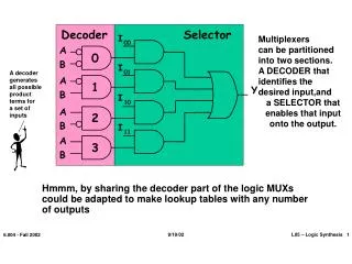
I. 0. 0. I. 0. 1. I. 1. 0. I. 1. 1. Decoder. Selector. Multiplexers can be partitioned into two sections. A DECODER that identifies the desired input,and a SELECTOR that enables that input onto the output. A. 0. B.

L05 – Logic Synthesis 1
E N D
Presentation Transcript
I 0 0 I 0 1 I 1 0 I 1 1 Decoder Selector Multiplexerscan be partitionedinto two sections. A DECODER thatidentifies thedesired input,and a SELECTOR that enables that inputonto the output. A 0 B A decodergeneratesall possibleproductterms fora set ofinputs A 1 Y B A 2 B A 3 B Hmmm, by sharing the decoder part of the logic MUXs could be adapted to make lookup tables with any number of outputs 9/19/02 L05 – Logic Synthesis 1 6.004 - Fall 2002
There’s anextra levelof inversionthat isn’tnecessaryin the logic. However,it reducesthe capacitiveload on themodule drivingthis one. These are just “DeMorgan”ized NOR gates This ROM stores 16 bitsin 8 words of 2 bits. Shared Decoding Logic Fixed “AND plane” Decoder A B Cin 0 1 2 3 7 4 5 6 S Cout Configurable Selector Configurable “OR plane” We can build a general purpose “table-lookup” device calleda Read-Only Memory (ROM), from which we can implementany truth table and, thus, any combinational device Made from PREWIRED connections , and CONFIGURABLEconnections that can be either connected or not connected 9/19/02 L05 – Logic Synthesis 2 6.004 - Fall 2002
T U V W X Y Z ROM-Based Design • Once we’ve written out the truth table we’ve basically finished the design Possible optimizations: - Addressing tricks Truth Table for a 7-sided Die - Eliminate redundant outputs 9/19/02 L05 – Logic Synthesis 3 6.004 - Fall 2002
DREG AOI.21 A B C D Q Z Standard Cells • First, a library of fixed-pitch logic cells (gates, registers, muxes, adders, I/O pads, …) are created. A data sheet for each cell describes its function, area, power, propagation delay, output rise/fall time as function of load, etc. 9/19/02 L05 – Logic Synthesis 4 6.004 - Fall 2002
Now put it in Hardware! 4 inputs 24 locationseach location supplies 4 bits ROM 16x4 unlock IN Current state Next state We assume inputs are synchronized with clock… 3 3 Trigger update periodically (“clock”) 9/26/02 L07 – FSMs 5 6.004 – Fall 2002