Download
1 / 18
190 likes | 372 Vues
Development of light-weight spherical mirrors for RICH detectors. RICH2007 6th International Workshop on Ring Imaging Cherenkov Counters Stazione Marittima, Trieste, Italy 15 - 20 October 2007. Fabio Metlica Bristol University-UK On Behalf of the LHCb Collaboration.

E N D
Development of light-weight spherical mirrors for RICH detectors RICH2007 6th International Workshop on Ring Imaging Cherenkov Counters Stazione Marittima, Trieste, Italy 15 - 20 October 2007 • Fabio Metlica • Bristol University-UK • On Behalf of the • LHCb Collaboration Technological aspects of Cherenkov detectors Friday 19 October 2007 RICH2007 in Trieste F. Metlica
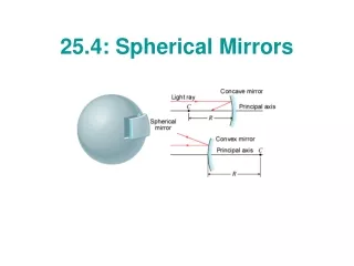
Introduction Light-weight mirrors are required in RICH detectors whenever the material budget must be minimized, to reduce particle interactions with the mirror material inside the detector acceptance. Twopromising light-weight mirror technologies were R&Ded for the spherical mirrors of the RICH1 detector in LHCb. The mirrors must satisfy the following requirements: -light-weight: radiation length <2%·X0; interaction length <1%·λI; -radiation hardness up to ~10kGy (equivalent to 10 years in LHCb); -compatibility with fluorocarbon radiator gas environment (C4F10); -good mirror rigidity and optical quality. RICH1-LHCb • glass-coated beryllium • carbon-fiber (chosen for RICH1) spherical mirrors F. Metlica
Introduction: Mirror Optical Quality Three important parameters define the mirror optical quality (measured at CERN): • Reflectivity: requirement ~90% in 200-600nm range; • R radius of curvature: RoCrequirement R±(1%·R); • Average geometrical quality D0: requirement D0<2.5mm; D0 is the diameter of circle at the mirror center of curvature (CoC) which contains 95% of the reflected light intensity from a point source placed at the CoC. D0 and R measurement: -point source illuminates uniformly whole mirror; -reflected image (spot) recorded by camera; -sliding table moves in 1mm steps, range 40mm; -smallest spot image D0,R; -σ(D0)~0.06mm and σ(R)~1mm. CERN lab setup to measure D0 and R mirror sliding table F. Metlica
Beryllium Mirror Technology Beryllium (Z=4) has unique properties ideal for lightweight applications: • “transparency” to particles; • radiation hard; • fluorocarbon compatibility; • non-magnetic; • light-weight; • good rigidity. Principal disadvantages: • high manufacturing costs; • high toxicity, requires safety measures for manufacturing and handling. Polished beryllium surfaces: ~50% reflectivity in visible and UV range; ~20-30 nm rms average surface roughness. High mirror reflectivity ~90% in visible and UV achievable by: -fusing a thin glass layer onto a beryllium substrate; -polishing glass surface and applying an Al reflective coating film. Comparison of properties for typical mirror materials X0: radiation length λI: interaction length E: Young’s Modulus α:coefficient of thermal expansion r: density F. Metlica
Beryllium Small Sized Prototypes Three small sized glass-coated beryllium prototypes manufactured in Russia and tested successfully at CERN. Prototype 1:flat mirror, 10mm Be + 1mm glass coating, D0<0.1mm, 3.6%·X0. Prototype 2:spherical mirror with rib-like support, 5-20mm Be + 1mm glass coating, D0=0.85mm, R=7926mm (design 8000mm), 3.3% ·X0. Prototype 3: spherical mirror rectangular shaped, 6mm Be + 0.3mm glass coating, D0=0.41mm, R=1696mm (design 1700mm), 1.9% ·X0. 2: spherical, rib-like 1: flat 3: spherical, rectangular shaped Good D0, and R close to the design value, <2%·X0. F. Metlica
Beryllium Full-Sized Prototype: Design Designed to be as thin as possible but rigid enough not to deform under its own weight. • 3mm thick beryllium substrate + 0.3mmglass coating; • rectangular shaped ~400mm x 660mm, size constrained by manufacturing limitations; • 20mm thick beryllium rim at one edge to support mirror; • R=2700mm (RICH1 specs). FEA (finite element analysis) done for beryllium substrate to study mirror support mechanism: • mirror stresses and distortions for different support schemes for mirror in RICH1, i.e. tilted ~120 w.r.t. vertical; • natural vibration modes; • calculate the effect on D0 due to the gravity deflection of the mirror: ~0.3mm. Central single point mirror support scheme chosen; best option based on FEA studies. central single point support FEA Mesh Model 3mm beryllium substrate max deflection 164μm deflection contour plot 20mm beryllium rim F. Metlica
Beryllium Full-Sized Prototype: Manufacture beryllium blank • Beryllium blanksproducedat Ulba in Kazakhstan: Powder Metallurgy and Vacuum Hot Pressing: beryllium powder placed in die; apply pressure, heat, vibrations (to homogenize) and vacuum (to outgas). • Beryllium blank machined at Kompozit (Moscow-Russia) Blank machined, grinded, annealed several times, and cut; ~4mm thick beryllium substratewith RoC close to final value. • Glass dressing at Vavilov (St. Petersburg-Russia) -glass type selected with coefficient of thermal expansion to match beryllium; -several thin glass sheets placed onto Be-substrate front face covering it; -placed in oven ~600oC to melt glass and then left to cool down; -glass polished with standard optical methods (~0.3-0.5mm thick); -fine tuning of RoC possible by glass polishing. • Mirror mount holes:titanium inserts glued (rad-hard) into holes of rim: -central insert bolted to support frame; -pins in side inserts as safety mechanism to prevent rotation. 80cm back view of beryllium substrate front view glass-coated beryllium substrate flat rim F. Metlica
Beryllium Full-Sized Prototype: Characterization • D0 = 3.3mm, R=2675mm: D0 out of specs (D0 <2.5mm) but tolerable. • Beryllium substrate ~3.8mm: high risk in breaking substrate during manufacture to reach 3mm. • Glass coating ~0.4mm: thinnest at center ~0.3mm up to ~1mm at edges, done to correct RoC. • Optical dead area due to air bubbles, holes and chamfer ~0.5% • ~1.6%·X0, ~1%·λI; weight 2.7 kg, size ~400mm x 660mm D0 spot at CoC • SUMMARY: • Overall optical quality good; • Within the requirements (except D0); • First ever large sized beryllium-glass-coated mirror having a thin • beryllium substrate and glass coating; • Refinement of manufacturing technique improved optical quality. front view of Be-glass-coated mirror: Al reflective film not applied F. Metlica
Carbon Fiber Mirror Technology (CFRP) Carbon fiber reinforced polymer (CFRP) used to fabricated light-weight mirrors. Mirrors fabricated at CMA (USA) and consist of: - carbon fiber (~70%): reinforcement material - resin (~30%): matrix material which binds fibers together (cyanate ester resin) Advantages: • light-weight: areal density ~6 kg/m2 equivalent to ~1.4%·X0, ~0.7%·λI; • cheaper than beryllium; • no safety implications. Potential disadvantages: uncertainty over • fluorocarbon compatibility; • radiation hardness. }tested successfully at CERN F. Metlica
CFRP: Prototype Testing Prototypes: • demonstration mirror: 600mm x 600mm, RoC=2200mm; • two small mirrors: 150mm, RoC=1890mm; • two flat carbon-fiber samples for mechanical tests (~0.5mm thick). Testing: Expose to either radiation or C4F10 but not to both. • Radiation: 10 kGy - in 3 steps with a total absorbed dose of 1 kGy, 4 kGy, 10 kGy; - 1 kGy equivalent to 1 year radiation in RICH1 environment; - gamma radiation; at Ionisos a Cobalt-60 facility near Lyon-France. • Fluorocarbons: ~1 year C4F10 -continuous exposure to C4F10 gas in tank at room temperature and pressure. 600mm demonstrationmirror 150mm flat sample ~100mm small mirror samples F. Metlica
CFRP: Testing of Prototype Mirrors • Demo Mirror: D0=1.0±0.15 mm; RoC=2205±3 mm; exposed to C4F10, mirror too large to measure refle. • Two small mirrors: D0=0.8±0.15mm and RoC=1890±3mm(for both mirrors); Reflectivity (small mirrors): -coating: 70 nm Al + 70 nm SiO (CMA coating); -CMA coating gives low reflectivity in the UV range. No change in optical properties after 10kGy and ~1 year in C4F10. CoC spot of demo mirror Do~1 mm Small Mirror 2 radiation exposure Small Mirror 1 C4F10 exposure F. Metlica
CFRP: Testing of Flat CF Samples Two flat CFRP samples(sample-A→ C4F10 exposure, sample-B→ irradiated): • mechanical properties: tensile (pulling) and flections (bending) tests; • average surface roughness (Ra): sample A: ~1.8±0.15μm sample B: ~1.7±0.15μm • comparison of microscope photos of surface: no noticeable change. flexural rigidity: ~33N/mm F(N) F(N) flection tests tensile rigidity: ~8kN/mm l(mm) l(mm) μm surface roughness profile tensile tests mm No noticeable change in mechanical properties after 10kGy and ~1 year in C4F10. microscope photo x100 flat sample B F. Metlica
CFRP: Production Mirrors Design • 4 mirrors of size ~640mm x 835mm; RoC=2700mm. • Honeycomb structure2 CFRP skin core cell reinforcement: -two “outer” edges reinforced with square cells; -rest reinforced with circular cells; -cells glued to back-face and front-face CFRP skins. • Areal density: ~ 5.5 kg/m2 (~1.3%X0) • 3-point mounting:points located at the periphery of mirror, outside the mirror acceptance • CFRP support frame: two C-halves joined at the center uncoated mirror 2 1 beampipe hole 3 4 CFRP frame square cells ~5.5 kg/m2; ~1.3% Xo CFRP skin FEA: max distortion of supported mirror ~ 3.5 μm beampipe cut-out glass mandrel core cell reinforcement on CFRP skin F. Metlica
CFRP: Fabrication by Optical Replication CFRP sheets glass mandrel replica mirror a)Mandrel (Pyrex glass): final polishing done at CMA. Pyrex coefficient of thermal expansion matches CF. b)CFRP pre-impregnated sheets and core cells are laid over the mandrel: several CFRP layers (~few 100μm thick, single direction) are laid in fixed orientations (e.g. pi/3), depending on shape and mechanical requirements, resulting in a quasi-isotropic material. c)Curing: heat, pressure, vacuum applied: CFRP material hardens and takes shape of the mandrel. d) Replica (CFRP) separated from the mandrel: Then vacuum coated with thin reflective film after cleaning surface. RICH1 mandrel being polished at CMA laying of CFRP sheets glass mandrel F. Metlica
CFRP Production Mirrors: Characterization • Ronchigram lines are reasonably straight • good spherical mirror surface(measured at CMA). • D0, R measurement: D0~1.2mm, R~2710mm • Mirror number D0(mm) R(mm) • #1 1.07 2710 • #2 1.15 2710 • #3 1.38 2709 • #4 1.18 2710 Ronchigrams of the lower set of mirrors, #3 and #4 uncoated production mirror on optics stand CoC Spot of Mirror 1 ~1mm Ronchigrams (diffraction grating placed near CoC) for good (left) and bad (right) mirror surfaces Production mirrors are of good optical quality and well within specs. F. Metlica
CFRP Mirrors: Reflectivity Coating (SESO) • Four production CMA mirrors coated at SESO (Aix-en-Provence, France) in Feb07. • CMA standard coating is Al+SiO (visible range). • Al(80nm)+MgF2(160nm) coating chosen for good reflectivity in visible and UV range (SESO). • SESO coated production mirrors: -average reflectivity ~90%; -reflectivity >85% in 200-600nm range. Reflectivity curves of production CMA mirrors SESO coated production mirror average reflectivity~90% F. Metlica
CFRP Production Mirrors in RICH1 CFRP mirror assembly on testing rig CFRP mirrors installed in RICH1 in July 2007 glass flat mirrors beampipe CFRP support frame 4 CFRP mirrors F. Metlica
Summary • Two technologies tested successfully for light-weight mirrors: • glass-coated beryllium and carbon-fiber. • Glass-coated beryllium: • -first ever large sized (~400mm x 660mm) beryllium glass-coated mirror • with a thin substrate (~4mm) ~1.6%·X0; • -overall optical quality good: D0=3.3mm; R=2675mm; • -improvement in mirror quality to be expect with the refinement of the manufacturing technique. • Carbon-fiber (CFRP): • -four large production mirrors for RICH1: ~640mm x 835mm; • -well within specs: D0~1.2mm;R~2710mm;~1.3%·X0, reflctivity~90% (200-600nm); • -testing: • fluorocarbons: ~1 year C4F10 exposure • radiation: ~10kGy (~equivalent to 10 years in RICH1) • Both technologies highly suitable for light-weight mirror applications. • Carbon-fiber (CFRP) chosen for RICH1 because very promising, • but also on grounds of delivery time and costs. }no change in opto-mechanical properties F. Metlica