Optical Parametric Devices
Optical Parametric Devices. David Hanna Optoelectronics Research Centre University of Southampton Lectures at Friedrich Schiller University, Jena July/August 2006. Outline of lecture series: Optical parametric Devices. Lecture1: Optical parametric devices: an overview


Optical Parametric Devices
E N D
Presentation Transcript
Optical Parametric Devices David Hanna Optoelectronics Research Centre University of Southampton Lectures at Friedrich Schiller University, Jena July/August 2006
Outline of lecture series: Optical parametric Devices • Lecture1: Optical parametric devices: an overview • Lecture2: Optical parametric amplification and oscillation: Basic principles • Lecture3: Ultra-short pulse parametric devices • Lecture4: The role of Quasi-Phase Matching in parametric devices, PLUS Brightness enhancement via parametric amplification
Lecture 1Optical Parametric Devices: an overview David Hanna Optoelectronics Research Centre University of Southampton Lectures at Friedrich Schiller University, Jena July/August 2006
Optical parametric amplification 3 – wave interactions SFG Energy conservation, ћω1, ћω2 annihilated, ћω3 created DFG ћω3 annihilated, ћω2, ћω1 created input ω2, wave is amplified (parametric amplification)
10-8 photon conversion efficiency, 10-6 % , 3x10⁻¹⁰ %/W 2006 Capability: ~1000%/W→13 orders in 45 years
Parametric gain: key information needed • Magnitude of gain, and its dependence on crystal length, pump intensity, crystal nonlinearity • Gain bandwidth, ie range of signal wavelengths that experience amplification For significant gain, need phase-matching k3 = k1 + k2 n3ω3 = n1ω1+n2ω2 (co-linear)
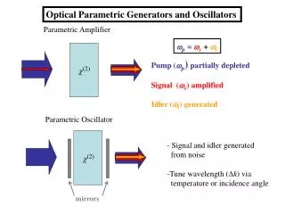
Parametric amplification and parametric noise ω3 ω1 Pump Idler (generated) > > ω2 ω2 Signal Signal (amplified) > > Transparent nonlinear (χ(2)) dielectric ω3 Pump > ω1 > > Amplified noise ω2 > > Input pump spontaneously generates pairs of photons ћω1, ћω2 (parametric noise) which are then amplified.
Optical parametric oscillation Pump Signal Idler Doubly-resonant oscillator (DRO) Pump Signal Idler Singly-resonant oscillator (SRO)
Parametric gain vs laser gain • Gain peak can be tuned, by tuning the phase-match condition (change tilt of crystal, or temperature, or QPM grating period). Very wide signal-idler tuning is possible. • Gain is produced at two wavelengths – two outputs. Choice of resonator (DRO or SRO). • Coherent relation between interacting waves; restriction on relative direction of the waves. No analogue of side-pumped laser. Finite range of allowed pump wave directions can amplify single signal wave. Multimode pump can be used. brightness enhancement
Parametric gain vs laser gain • Gain only present while pump is present. No storage of gain/energy No equivalent of Q-switching. Few OPO round trips if nsec Q-switched pump pulses are used. • Gain is determined by peak pump intensity: very high gain with intense ultrashort pump pulses. • No energy exchange with nonlinear medium – only exchange between the interacting waves. No heat input to the medium
Parametric devices Pump > Signal > > Idler Oscillators: SRO or DRO, pump: single-pass, double-pass or resonated, cw or pulsed. long pulse (many round trips), or train of short pulses, SPOPO (synchronously pumped OPO) OP Amplifier: input signal provided OP Generator: no input signal, output generated by amplification from parametric noise
Synchronously-pumped OPO > > Signal and idler output pulse train Mode-locked pump: pulse separation matches round trip of OPO N.L.Xtal > > > • OPO gain corresponds to the peak power of the pump pulse • Crystal length must be short enough so that group velocity dispersion does not separate pump, signal and idler pulses in the crystal.
Attractions of SPOPO • Low threshold average power • Synchronised outputs at two wavelengths (e.g. for CARS) • Very high gain possible, can oscillate even with very high idler loss • Very high efficiency, e.g. makes the tandem OPO practical
Quasi-Phase-Matching Proposed Armstrong, Bloembergen, Ducuing, Pershan, Phys Rev 27,1918,(1962)
Periodic-poling scheme (e.g. as in PPLN) 4lc Period = 2lc 1st order phase-matching ESH Phase-matched 3lc c -cc -cc -c Quasi- phase- matched 2lc lc lc lc 2lc 2lc period 4lc 3lc ESH after each lc is p/2 smaller than for perfect phase-matching over the same length of medium. So, effective nonlinear coefficient reduced by p/2.
Some benefits of QPM Access materials having too low a birefringence for phase-matching, e.g. LiTaO3, GaAs Ability to phase-match any frequencies in the transparency range, freedom to choose ideal pump for an OPO Non-critical (90°) phase-matching, allows tight (confocal) focussing Access to largest nonlinear coefficient, e.g. d33 in LiNbO3
Periodically Poled Lithium Niobate Crystal Acknowledgements to Peter Smith, Corin Gawith and Lu Ming ORC, University of Southampton
Frequency-conversion efficiency and parametric gain in PPLN SHG conversion efficiency, confocal focus (l = b = 2π wo2n1/λ) (ω1→ 2ω1) ~ 16π2P(ω1)d2effl/cє0n1n2λ13 SHG, 1064nm → 532nm or Parametric gain 532nm → 1064nm ~2%/ Wcm (deff = 17pm/V) (Waveguide enhancement by lλ/2nw2~102 -103 ; >1000%/ Wcm2) Parametric gain, 1µm → 2µm, ~0.25% / Wcm (PPLN) 2µm → 4µm, ~0.5% / Wcm (GaAs)
Minimum pump power/energy for 1µm – pumpedPPLN parametric devices cw SRO ~1-3W Nanosecond-pumped OPO ~5 µJ Synchronously-pumped OPO ~100pJ (~10 mW @ 100 MHz) Optical parametric generator ~100nJ (fs/ps) ~100µJ (1 nsec) 130 dB gain All power/energy values scale as (d2/n2λ3)-1
CW singly-resonant OPOs in PPLN • First cw SRO: Bosenberg et al. O.L., 21, 713 (1996) 13w NdYAG pumped 50mm XL, ~3w threshold, >1.2w @ 3.3µm • Cw single-frequency: van Herpen et al. O.L., 28, 2497 (2003) Single-frequency idler, 3.7 → 4.7 µm, ~1w → 0.1w • Direct diode-pumped: Klein et al. O.L., 24, 1142 (1999) 925nm MOPA diode, 1.5w thresh., 0.5w @ 2.1µm (2.5w pump) • Fibre-laser-pumped: Gross et al. O.L., 27, 418 (2002) 1.9w idler @ 3.2µm for 8.3w pump
Some results from PPLN ps/fs parametric devices • Low threshold SPOPO; 7.5 mW (av), 1047nm pump, 4ps, @120 MHz 21mW, pumped by Yb fibre laser • High gain devices (at mode-locked rep. rate) Widely-tuned SPOPO, idler >7µm OPCPA, 40 dB gain, mJ output OPG operated at 35 MHz, ~0.5W signal • High average power femtosecond SPOPO 19W (av) signal @ 1.45 µm, 7.8W @ 3.57 µm
SPOPO facts and figures • Average output power > 20 W • Shortest pulses 13 fs • Tuning range 0.45 – 9.7 micron • Efficiency (diode laser OPO) 25% • Slope efficiency >100% (170% observed)
PPLN Waveguide Optical Parametric Generator ~2ps, 200pJ, (100W) pump @ 780nm gives ~100dB gain @1550nm 10dB needs a pump Power of 1W Xie Xie et al JOSA B, 21, 1397, (2004)
Two spatial-mode waveguide parametric amplifier OPG threshold: 300pJ , 2ps @ 780nm Xie & Fejer, Optics Letters, 31, 799, (2006)
OPCPAOptical Parametric Chirped Pulse Amplification Butkus et al Applied Physics B, 79, 693 (2004)
The OPCPA march towards Petawatts Dubietis et al IEEE J Sel Topics in QE,12, 163, (2006)
Brightness Enhancement via Parametric Amplification • Although parametric amplification requires a high-brightness pump, this does not imply a perfect, diffraction-limited pump. • A range of pump wave angles (modes) can effectively pump a SINGLE signal wave (mode). • So the amplified signal wave can be brighter than the input pump. ▼ Brightness Enhancement (and no heat input)
Angular acceptance of pump I ΔkL = π sets limit to θ Next: relate Δk to θ Angular acceptance: determined by the phase-mismatch, Δk, that can be tolerated Δk kp ki θ ks ki kp Δk
Concluding remarks • Χ(2) Parametric processes now have the pump sources they need and deserve. • Χ(2) Parametric devices are very versatile cw to femtosecond UV to TeraHertz mW→TW→PW • Absence(?) of heat generation in active medium is of growing interest. • Caveat: There is not an abundance of suitable χ(2) nonlinear media.