Download
1 / 20
270 likes | 435 Vues
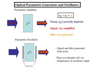
(2). p = s + i. Pump ( p ) partially depleted Signal ( s ) amplified Idler ( i ) generated. Parametric Oscillator. Signal and idler generated from noise Tune wavelength ( k ) via temperature or incidence angle. (2). mirrors.

E N D
(2) p = s+ i Pump (p)partially depleted Signal (s) amplified Idler (i) generated Parametric Oscillator • Signal and idler generated • from noise • Tune wavelength (k) via • temperature or incidence angle (2) mirrors Optical Parametric Generators and Oscillators Parametric Amplifier
Early 1990s A single 266 nm pumped BBO OPO 2400 nm Ar-ion Laser Kr-ion Laser He- Cd Lasers He-Ne Lasers GaAlAs Lasers N Laser Ti:Sapphire InGaAsP Diode Lasers Alexandrite Laser Ruby Laser & 2nd Harmonic Nd YAG Laser and 2nd and 3rd Harmonics XeFExcimer Lasers XeCl Dye Lasers (7-10 different dyes) Color Center Lasers 900 1100 700 300 1300 Wavelength (nm)
OPA: Undepleted Pump Approximation The strong “pump” beam at cis undepleted. i.e. The weak “signal beam at a is amplified. An “idler” beam at bis generated A pump beam photon breaks up into a signal photon and idler photon
Clearly the functional behavior depends on the sign of 2. • The behavior near and on phase match (2>0) is exponential growth • When 2<0, the behavior is oscillatory. • Using the boundary condition
z Exponential Gain Coefficient For this difference frequency process, the larger the intensity gain coefficient 2, the broader the gain bandwidth! This is contrast to SHG (i.e. sum frequency case) in which the bandwidth narrows with increasing intensity
No gain! • Notes: • For large , low level oscillations still exist, but are too small to be seen • The zero level is different for . • For there is no signal gain, just • energy exchange with the idler as shown above. z
OPA Numerical Example Assume k=0 Single pass gain is 34%
OPA Solutions with Pump Depletion Note: This amplifier response is periodic in distance and pump power. Therefore there is no saturation as with other amplifiers. The gain is exponential, but only over a finite range of length. For small distances the signal growth is not exponential although the idler growth is!
c (2) a b Singly Resonant Oscillator Doubly Resonant Oscillator Cavity modes at both signal and idler frequency need to be considered Have to deal with cavity modes at signal frequency Optical Parametric Oscillators (OPOs) OPOs are the most powerful devices for generating tunable radiation efficiently. Put a nonlinear gain medium in a cavity, “noise” at a and b is amplified. By using a cavity, the pump is depleted more efficiently. Using a doubly resonant cavity (resonant at both the idler and the signal), the threshold for net gain is reduced substantially. Triply resonant cavities (also resonant at the pump frequency) have been reported, but their stability problems have limited their utility and commercial availability Assume that pump is essentially undepletedon a single pass through the cavity
Forward Backward Doubly Resonant Cavity Threshold Condition • Idler (b) and signal (a) beams experience gain in one direction only, • i.e. interact with (c) pump beam only in forward direction) • -Cavity “turn-on” and “turn-off” dynamics is complicated we deal only with steady state (cw) • Assume lossless (2) medium • Only loss is due to transmission through mirrors • Steady state occurs whendouble pass loss equals single pass gain! After interacting in forward pass with pump beam inside the cavity (2)
Reflection Reflection Linear phase accumulation Linear phase accumulation - In addition, since the mirrors are coated for high reflectivities at band a, they accumulate phase shifts of 2kbL and 2kaL respectively after a single round trip inside the cavity. Steady state after one round trip
Gain threshold: For minimum threshold, 2kbL=2mb and 2kaL=2ma
→ Discrete cavity mode frequencies with separations depends on cavity modes fixed by pump Signal and idler are both standing waves in cavity OPO Instabilities: Doubly Resonant Cavity Mechanical instabilities (vibrations, mount creep and relaxation..) and thermal drift cause cavity length changes and hence output frequency changes Cavity resonances on which threshold is minimum Non-degenerate integers How many cavity modes exist within the gain bandwidth? Many cavity modes within gain bandwidth
Gain Coefficient a b “Mode hop” If length or changes, the next operating point when cavity modes coincide can cause a large shift (called a “mode hop”) in output frequency quite a modest intensity! Note that when a drifts up in frequency, b drifts down in frequency! OPO oscillates when cavity modes coincide e.g. Type I birefringent phase matched LiNbO3d31=5.95pm/V, L=1cm c=0.53ma=b=1.06m (near degeneracy) nanbnc2.24,Ra=Rb=0.98
Singly Resonant OPO (SRO) Cavity is resonant at only one frequency, usually the desired signal (a) Ra1 Rb0 Threshold much higher for SRO than for DRO e.g. The threshold for the previously discussed LiNbO3 case is 1 MW/cm2 Stability of Singly Resonant OPO If the cavity drifts, the output frequency drifts with it, no large mode hops occur. Frequency hops will be just the mode separation.
“slope efficiency” OPO Output At threshold, gain=loss. If I(c) > Ith(c), input photons in excess of threshold are converted into output signal and idler photons One pump photon is converted into one signal and one idler photon. How much comes out of OPO depends on the mirror transmission coefficients
y x z Frequency Tuning of OPO Two approaches: (1) angle tuning (2) temperature tuning (relatively small – useful for fine tuning In general requires numerical calculations Angle Tuning (uniaxial crystal) e.g.
Examples of OPOs Example of Angle Tuning Example of Temperature Tuning LiNbO3(birefringence phase-matched)
Mid-infrared OPA and OPO Parametric Devices Atmospheric transmission and the molecules responsible for the absorption Need broadly tunable sources for pollution sensing applications
Materials NPP: N-(4-nitrophenyl)-L-propinol DMNP: 3,5-dimethyl-1-(4-nitrophenyl) pyrazole DAST: Dimethyl-amino-4-N-methylstilbazolium tosylate