Chapter 6 Series-Parallel Circuits
Chapter 6 Series-Parallel Circuits. Examples of Series-Parallel Circuits. Basic Configurations. An Example for Analysis: Series Circuits Connected in Parallel. Team Activity: Problem 1 on p. 173 – Method 1. Use the voltage divider method to calculate the voltages across R 1 & R 2 .

Chapter 6 Series-Parallel Circuits
E N D
Presentation Transcript
Basic Configurations EGR 101
An Example for Analysis:Series Circuits Connected in Parallel EGR 101
Team Activity: Problem 1 on p. 173 – Method 1 • Use the voltage divider method to calculate the voltages across R1 & R2. • Use the voltage divider method to calculate the voltages across R3 & R4. • Calculate the current through R1 & R2. • Calculate the current through R3 & R4. • Calculate the total current IT. EGR 101
Team Activity: Problem 1 on p. 173 – Method 2 • Find the equivalent resistances R12 & R34. • Find the total resistance RT. • Find the total current IT. EGR 101
A Second Example:Parallel Circuits Connected in Series EGR 101
Team Activity: Problem 5 on p. 174. • Find the equivalent resistances R12 & R34. • Calculate the total current IT. EGR 101
Wheatstone Bridge Galvanometer – a sensitive ammeter EGR 101
Bridge Operation – based on three possible states: VA = VB VA > VB VA < VB EGR 101
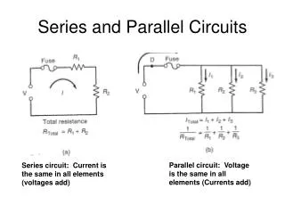
Wheatstone Bridge: A series-parallel arrangement at “balance” • Resistors R1 and R2 are in series • R12 = R1 + R2 • Resistors R3 and R4 are in series • R34 = R3 + R4 • Equivalent resistance R12 is in parallel with equivalent resistance R34 EGR 101
Circuit Analysis at “balance”, galvanometer current =0 EGR 101
Application of a Wheatstone Bridge:Smoke Detector Photoconductive Cells – Light-Controlled Resistors Used as Sensor and Reference When the amount of light striking the device increases, the resistance decreases (and vice-versa). EGR 101
Detector Diagram EGR 101
How it works When the air is clear, the bridge is balanced. If smoke enters the lower chamber via the vents, the resistance of the lower photoconductive cell increases, causing the bridge to become unbalanced, triggering the alarm. SMOKE EGR 101