
Uploaded by
della
0 SLIDES
233 VUES
10LIKES
Series vs. Parallel Circuits
DESCRIPTION
Series vs. Parallel Circuits. Concept Presentation by: Diana Restua Haxhi Dvorani. Concept Overview. Components of an electrical circuit can be connected in many different ways. The two simplest of these are called series and parallel and occur very frequently.
Download

1 / 0
Télécharger la présentation 
Series vs. Parallel Circuits
An Image/Link below is provided (as is) to download presentation
Download Policy: Content on the Website is provided to you AS IS for your information and personal use and may not be sold / licensed / shared on other websites without getting consent from its author.
Content is provided to you AS IS for your information and personal use only.
Download presentation by click this link.
While downloading, if for some reason you are not able to download a presentation, the publisher may have deleted the file from their server.
During download, if you can't get a presentation, the file might be deleted by the publisher.
E N D
Presentation Transcript
-
Series vs. Parallel Circuits
Concept Presentation by: Diana Restua Haxhi Dvorani - Concept Overview Components of an electrical circuit can be connected in many different ways. The two simplest of these are called series and parallel and occur very frequently. Series connection contains parts connected along in a single path, so the same current flows through. Parallel connection has components connected in a way that the same voltage is applied to each component. A circuit composed solely of components connected in series is known as a series circuit; likewise, one connected completely in parallel is known as a parallel circuit. Combination of both makes combined circuits In a series circuit, the current flow through each of the components is the same, and the voltage across the components is equal to the sum of the voltages across each component. In a parallel circuit, the voltage across each of the components is the same, and the total current is the sum of the currents through each component.
- Curriculum Expectations E2.1 use appropriate terminology related to electricity, including, but not limited to: ammeter, amperes, battery, current, fuse, kilowatt hours, load, ohms, potential difference, resistance, switch, voltmeter, and volts [C] E2.5 design, draw circuit diagrams of, and construct series and parallel circuits E2.6 analyse and interpret the effects of adding an identical load in series and in parallel in a simple circuit [AI, C] E2.7 investigate the quantitative relationships between current, potential difference, and resistance in a simple series circuit [PR, AI] E2.8 solve simple problems involving potential difference V, electric current I, and resistance R, using the quantitative relationship V = IR [AI, C]
- Lessons Sequence Lesson 1 Review Schematic Diagrams and types of Electrical Circuits Using schematic diagrams to simplify circuit graphical representation Lesson 2 Electrical Resistance and Ohm's Law Relationship amongst Current, Voltage and Resistance Lesson 3 Properties of Series Circuits Total Resistance in Series Circuits Lesson 4 Properties of Parallel Circuits Total Resistance in Parallel Circuits Lesson 5 Combined Circuits and Applications Equivalent Resistor of a Combined Circuit
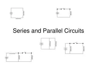
- Schematic Diagrams Electric circuits, whether simple or complex, can be described in a variety of ways. An electric circuit is commonly described with mere words. Ex. "A light bulb is connected to a D-cell" is a sufficient amount of words to describe a simple circuit. Another means of describing a circuit is to simply draw it. This method provides a quicker mental picture of the actual circuit. A final means of describing an electric circuit, is by use of conventional circuit symbols, to provide a schematic diagram of the circuit and its components
- Electrical Symbols The following diagram shows some of the most common circuit symbols
- Ohm's Law Ohm's Lawstates that the current in a circle is directed proportional to the applied voltage, and inversely proportional to the amount of resistance. I = V/R or V = IR This means that if the voltage goes up, so does the current flow, also when resistance goes up the current goes down. Ohm's Law is one of the most useful relationships in the study of electric circuits. It is used in the design of circuits that range in complexity from toasters to advanced computer systems YouTube link to the video
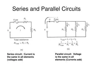
- Series Circuit A series circuit is a connection in which the components of the circuit (resistors) are wired to one another in a single path. It can be visualized as a race track with several turns The current is the same through each resistor, but the potential difference (voltage) around each resistor is not, and can be found using Ohm's law for that part of the circuit.
- Parallel Circuit A parallel circuit is a connection in which the resistors are arranged with their heads connected together, and their tails connected together. A parallel circuit is more like city streets that race tracks. Cars can have many pathways to travel. One might be a six lane highway, while another is a two lane side street. The voltage across each resistor in parallel is the same, but the current is not and can be found using Ohm's law.
- Series vs Parallel Table Summary Potential Difference, Current and Resistance in Series and Parallel
- Series vs Parallel Table Summary (cont...) Resistance, Current, and Voltage in Circuits
- Combined Circuits Many circuits have a combination of series and parallel resistors. The current flowing through each resistor can be found using Ohm's law for each part of the circuit that contains a resistor The total resistance is found by reducing the different series and parallel combinations step-by-step to end up with a single equivalent resistance for the circuit. This allows the current to be determined easily.
- Practical Applications Lighting Dimming the lights using a potentiometer (variable resistor) Build a circuit that has a light which can be independently turned on and off from two different locations using a three way switch Is it better to use series or parallel circuits to connect the Christmas lights? How many 15W Christmas, light can be connected in a 15 amp breaker knowing the power of a light is given by the formula P = V*I Wiring In what kind of circuit are home appliances connected to, that allows them to operate independently? What's the role of a circuit breaker in our homes? How electricians decide whether they are going to install a 15amp, 20amp or 30 amp circuit breaker?
- Teaching Strategies Debate (Group Work) Series vs. Parallel Circuit - stating differences and discussing about the usage of each circuit. or (Individual Work) Make a poster/presentation/song titled Series vs Parallel Circuits stating all the differences that were discussed. Lab Station (Group Work) Activity # 1. Series and Parallel circuit analysis. Build a series and parallel circuit according to the given direction, using a virtual circuit simulator Draw a schematic diagram of each circuit.
- Teaching Strategies (cont..) Activity # 2. Investigating Ohm's Law Following given diagrams, build the circuits and measure the C, V, R and compare the results with your calculations. Activity # 3. Resisting the Flow Use different types of resistors to build series and parallel circuits. Using voltmeter and ammeter measure and record the data in tables. Use Gizmos form Explore Learning Build circuits following directions from student exploration sheet and calculate the total resistance for each scenario
- Differentiated Assessment Students can choose for the project to: Work in group debate (Auditory) Work individually and prepare a presentation (Visual) Write a song/poem about series and parallel circuits (Musical). The song provided may serve as an inspiration Other activities such as: Building circuits (Kinesthetic) Gizmo group work (Interpersonal) Comparing circuits, recording and classifying data and calculating results (Logical) will create conditions for a differentiated assessment and a fair learning environment.
- Safety Considerations Students will be instructed how to safely operate electrical equipment, especially those involving voltages over 24 V (individual human tolerance varies greatly) Only CSA approved electrical equipment should be used. Equipment should be checked to ensure connections are tight and that there are no damaged or loose wires All electrical circuitry must be checked by the teacher before the switch is closed where there is the possibility of harm to students or damage to electrical equipment Students should be warned that dry cells may explode if shorted out (short circuited) Wires which short circuit dry cells become extremely hot and may cause burns when touched, or fires if in contact with flammables.
- Resources Books: Plumb, D. A. (1999). Science 9. Scarborough, Ont.: Nelson Canada. Wolfe, E. (1999). Sciencepower 9: science, technology, society, environment. Toronto: McGraw-Hill Ryerson. Reid, M.A (2009). Investigating Science 9: Canada Nelson, (2010). Science Perspective 9: Toronto: Nelson Educ Ltd. Web sites: http://www.allaboutcircuits.com/vol_1/chpt_5/1.html http://physics.bu.edu/py106/notes/Circuits.html http://www.explorelearning.com/ http://www.colorado.edu/physics/phet/simulations/cck/cck.jnlp


More Related