Download
1 / 31
310 likes | 336 Vues
Learn about MPI/Fiber analysis for fiber filled materials, including its importance, running the analysis, and interpreting the results. Explore the various types of fillers and their effects on the mechanical properties of composite materials.

E N D
Introduction • Aim • Introduce MPI/Fiber, background, running, interpreting results • Why do it • Critical to use MPI/Fiber when going to Warp and Stress with a fiber filled material • Overview • Background of fiber analysis is reviewed • Analysis results are interpreted
What is MPI/Fiber • Also called • Fiber analysis • Fiber flow analysis • Module used to calculate • Orientation of short fiber fillers in the molded part • Resulting thermo-mechanical properties of the composite part • Fiber orientation significantly affects • Shrinkage • Warpage
Running MPI/Fiber • Need • License of MPI/Flow • License of MPI/Fiber • Fiber filled material • Can be used with all 3 mesh types • Outputs are used in • MPI/Warp • (all 3 mesh types) • MPI/Stress • (Midplane only)
Why Run MPI/Fiber • Fiber orientation is the main cause of warpage for fiber filled thermoplastics • Fibers changes the mechanical properties of the composite • Fiber orientation varies with • Flow front shape • Thickness • Geometry • Must optimize fiber orientation to solve warpage problems
Why use Fillers • Fillers improve the material matrix properties • Increased stiffness • Increased strength • Reduced creep and stress relaxation over time • Time dependant properties • Increased upper temperature use limits • Improved dimensional stability • Reduced material costs • Increased electrical and thermal conductivity
Types of Fillers • Reinforcing Fibers • Glass, carbon, fibrous minerals, boron, kevlar • Increased flexural stiffness (modulus) • Increased tensile strength • Reduced creep and stress relaxation over time • Increased heat deflection temperature • Improved dimensional stability (reduced shrinkage) • Conductive Fillers • Carbon fiber, graphite, aluminum powders • Increased electrical conductivity • Improved thermal conductivity
Types of Fillers • Coupling Agents • Silanes, titanates • Improved interface bonding between matrix and fibers • Flame Retardants • Chlorine, bromine, phosphorous, metallic salts • Reduces occurrence and spread of combustion • Extender Fillers • Calcium carbonate, silica, clay • Reduces material cost
d length Filler vs. Fiber • MPI/Fiber is used to analyze fiber filled thermoplastic materials • Only fillers with aspect ratio greater than 1 are analyzed in MPI/Fiber (shape of fiber ) • Aspect ratio • The ratio of the longest side to the shortest, or length divided by diameter l/d • AR < 1, flakes • AR =1, cubes or spheres • AR > 1, fiber like
Aspect Ratios for Different Fillers • Aspect ratio < 1 • Glass, metal, mica • Aspect ratio = 1 • Talc, minerals • Typical aspect ratio for fibers = 25 • Average/default aspect ratio for short fiber • Glass, carbon, kevlar • Highest aspect ratio allowed = 5.0+E6 • Long fibers are broken up passing through the machine • A high aspect ratio fiber can be run with the short fiber assumption
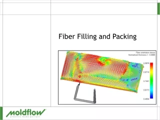
All standard flow analysis results Average Fiber Orientation Fiber Orientation Tensor Poisson’s Ratio Shear Modulus Tensile Modulus 1st principal direction 2nd principal direction - perpendicular to 1st Linear Thermal Expansion Coefficient 1st principal direction 2nd principal direction - perpendicular to 1st Results from MPI/Fiber MPI/Fiber results are symmetrical through the thickness unless a cooling analysis has been run
General Orientation Ellipsoid • Used to describe the fiber orientation • Graphically defines second order tensor • A – 9 components of the coordinate system or • B – Eigenvalues and C - Eigenvectors • Eigenvalues – statistical proportions 0 to 1 of alignment • Eigenvalues – principle directionof fiber orientation • For display the 3D ellipsoid • Projected to a plane forming aplane ellipse
Orientation Tensor • Txx – Magnitude of alignment in global X direction • Tyy – Magnitude of alignment in global Y direction • First principal value – magnitude of alignment in direction with most alignment • Default • Most useful
A - Random B C- Aligned Orientation Results • A – Fibers random in plane of element • B – Most fibers aligned in X direction • C – All fibers aligned in X direction • D – Principal alignment not in X direction D
MPI/Fiber Input to Warp and Stress • Layer based data used as input include • Fiber orientation • Mechanical properties • Elastic modulus • Shear modulus • Poisson’s ratio • Thermal expansion coefficients • In-cavity residual stress • Can be exported to other structural analysis packages
Filler type Weight fraction - converted from Weight fraction Fiber density Composite density Aspect ratio Density Thermal properties Specific heat Thermal conductivity Mechanical data Elastic modulus Poisson’s ratio Coefficient of thermal expansion Shear modulus Fiber Property Requirements
Fiber Properties Highlight the filler Click Details to see the properties
Material Properties • Mechanical Properties tab is the composite (polymer + filler) • Fiber properties are mechanical properties of the filler • Matrix properties are for the base polymer (no filler) • Solver uses Fiber properties and Matrix properties • If Matrix properties don’t exist they are calculated by the flow solver
MPI/Fiber Assumptions • Short fiber analysis • Long glass fibers are assumed to break in the machine so they will be “short” when entering the part • Fibers are evenly distributed throughout the volume • Fibers align • Parallel to flow direction in high shear rate areas • Transverse or random to flow direction at the center line • Fiber to fiber interaction is considered, Ci • Variation of orientation based on thickness is also considered, Dz
Fiber and Warp • Warpage analysis uses fiber results when available • Warpage results most accurate with CRIMS shrinkage data
High Shear Rate Stretching Flow Fiber Orientation • Fiber orientation is complex • Two rules of thumb exist • High shear rate • Tend to align fibers in the direction of flow • Stretching flows • Tend to align fibers in direction of stretching • A radial flow pattern fibers are aligned perpendicular to the flow
Mold Wall Direction 1 Velocity Profile Shear Rate Center Line 0,9 0,8 0,7 0,6 0,5 Direction 1 a11 0,4 0,3 0,2 0,1 0 Thickness 0.75 -1 -0.75 -0.5 -0.25 0 0.25 0.5 1 Layers through the thickness Fiber Orientation
Converging vs. Diverging Flow A = Entrance: Random Fibers B = Converging Flow: Flow aligned Fibers C = Diverging Flows: Transverse Alignment
Other Factors Affecting Orientation • Part geometry • Processing conditions • Filling speed - most influence • Thicker core and thinner skin layers • Fiber average aspect ratio and concentration • Increased aspect ratio and concentration • Yields increased flow aligned orientation
Running a Fiber Analysis • Select a polymer material with fiber content • In the Process Settings Wizard select • Check - Fiber orientation analysis if fiber material • Checked by default • Optional - Fiber parameters
Fiber Parameters • Calculate fiber interactions using • Auto-calculated Ci and Dz values (Default) • Dz based on average part thickness, Ci calculated using Dz • Auto-Calculated Dz Specified Ci • Specified Ci and Dz • Fiber inlet condition at gate • Fibers aligned at skin/transverse at core • Fibers aligned at skin/random at core
Composite Property Calculation Options • Information included for research and development in the fiber code • Default values appropriate for most conditions • Not recommended to change
Reviewing Midplane and Fusion Results • Tensor Principal values • First – Default • Shows alignment in direction of alignment • Tensor components • Alignment based on coordinate system Tensor principal values Tensor Components (Txx)
Reviewing 3D results • Tensor Principal values • First – Default • Range from ~0.33 to 1 • 3D random = 0.33 • In plane random 0.5 • Fully aligned 1.0
Cover, Fusion model Use Capron 8233GHS Evaluate the current gating location Review results Fill time Pressure Average fiber orientation Fiber orientation tensor Manifold, 3D model Use Capron 8233GHS Review results Fill time Pressure Fiber orientation tensor Exercise