Download
1 / 33
330 likes | 469 Vues
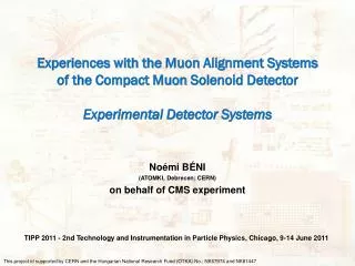
Experiences with the Muon Alignment Systems of the Compact Muon Solenoid Detector Experimental Detector Systems. No é mi B É NI (ATOMKI, Debrecen; CERN) on behalf of CMS experiment. TIPP 2011 - 2nd Technology and Instrumentation in Particle Physics, Chicago, 9-14 June 2011.

E N D
Experiences with the Muon Alignment Systems of the Compact Muon Solenoid DetectorExperimental Detector Systems Noémi BÉNI (ATOMKI, Debrecen; CERN) onbehalf of CMS experiment TIPP 2011 - 2nd Technology and Instrumentation in Particle Physics, Chicago, 9-14 June 2011 This project id supported by CERN and theHungarian National Research Fund (OTKA) No.: NK67974 and NK81447
Outline • CMS Muon System • Motivation / Challenge • CMS Muon Alignment Systems • Barrel • Endcap • Link • Calibration/Installation/Commissioning and Operation • Track-based Alignment • Offline data analysis • Barrel • Endcap • Impact on Physics • Twist lesson • Conclusion and Outlook TIPP 2011 - 2nd Technology and Instrumentation in Particle Physics, Chicago, 9-14 June 2011
CMS MuonSystem Return iron Yoke in red Endcap Disks: Cathode Strip Chambers (CSC) Y Length: 21 meter Height: 15 meter Solenoid: 3.8 Tesla X Global System of Coordinates Yoke Endcap: YE MuonBarrel (MB) stations MuonEndcap (ME) stations Yoke Barrel: YB Barrel wheels: Drift Tubes (DT) Resistive Plate Chambers (RPC) in both barrel and endcap Z Barrel: 4 DT stations in 5 iron wheels and 12 (3) or 14 (1) phi-sectors: 250 chambers 2 Endcaps: 4 CSC stations mounted on 3 iron disks and 18 (3) or 36 (5) phi-sectors: 468 chambers TIPP 2011 - 2nd Technology and Instrumentation in Particle Physics, Chicago, 9-14 June 2011
Motivation / Challenge • Huge magnetic field (3.8T) • Magnetic forces (~10K tons) displace, rotate and deform yoke elements by several mm • Yoke elements are HEAVY • Distortions due to gravity observed at the level of several mm • Yoke wheels/disks are movable • Position reproducibility for such large & heavy structures expected at the mm level at best • Thermal instability effects might contribute at the sub-mm level • Muon Alignment system must track these effects after CMS is closed and magnet is On • Tight spatial confinement • Tolerance to large (3.8T) magnetic fields • Tolerance to large radiation exposure TIPP 2011 - 2nd Technology and Instrumentation in Particle Physics, Chicago, 9-14 June 2011
CMS Muon Alignment Systems TIPP 2011 - 2nd Technology and Instrumentation in Particle Physics, Chicago, 9-14 June 2011
Barrel Alignment System Diagonal connection LED Passive Plane (6) Active plane (6) lens+diaphragm (384 x 288 px 1px = 12 x 12 μm 8-bit) Muon chamber L= 500 – 3000 mm optical line Z bar (8 lines) 20,30,70 mm sensor MAB (36 pieces) Link line • Alignment of 250 Drift Tube chamber w.r.t each other • Redundant network of optical connectionsbuilt from cheap LEDs and Video cameras • 10000 LEDs mounted on DTs read by ~600 cameras on 36 MABs (Module of the Alignment of Barrel) • Each MAB has one Board computer(read-out, control) • Rigid carbon fiber structuresattached to Barrel YokeYB±2 MABs containLink & Endcap components • Z-bars equippedwith LEDs and read byactive MABs provide betterZ-resolution • Calibration of single elements was needed before installation muon chambers CCD’s MAB Singleopticalmeasurement Image taken of forks installed on a chamber. Larger dots belong to the closer fork, while smaller dots are spots of the farther fork. The real spots can be seen inside the red markers. The others spots are reflections from the Alignment passage light sources (LED) TIPP 2011 - 2nd Technology and Instrumentation in Particle Physics, Chicago, 9-14 June 2011
Endcap Alignment • Relative alignment Cathode Strip Chambers (CSC) w.r.t. each other. Measure the bending and the relative Z position of the YEs w.r.t. each other • Network of optical connections complemented by clinometers, axial and radial distance meters. • Straight LineMonitors (SLM): • 3 per MuonEndcap(ME) station • Laser lines read by • Digital CCU Optical Position • Sensors (DCOPS) • Z-sensors • Relative z distance • between ME • stations • Transfer lines • SLM cross z, measure • relative x,y displacements • between ME stations Each SLM measures only 4 CSC, therefore the Endcap System measures only about the 1/6 of all CSC TIPP 2011 - 2nd Technology and Instrumentation in Particle Physics, Chicago, 9-14 June 2011
Link Alignment rφplanes • Simultaneous Monitoring and Alignment of DTs and CSCs in a common frame of reference related to the tracker through a network of optical connections • Lasers sources housed in rigid structures: • Alignment Rings (AR) attached to the tracker • Link Disks (LD) at Yoke EndcapsYE±1 • Module of the Alignment of Barrel(MAB) • Read by optical 2D sensors, • Amorphous Silicon-strip Position Detectors (ASPD) • On MuonEndcapME±1 chambers and on MABs on Yoke Barrel YB±2 • Complemented by clinometers and axial and radial distance meters • Organized into three rφ planes staggered 60º in φ (to match YB 12-fold geometry) • Each plane consists of four independent quadrants for a total of 12 Link quadrants (6 on each zCMS side) rzplane TIPP 2011 - 2nd Technology and Instrumentation in Particle Physics, Chicago, 9-14 June 2011
CMS MuonAlignment System YB+2 YE+1 DCOPS LD AR Link line MAB ASPDs SLM TIPP 2011 - 2nd Technology and Instrumentation in Particle Physics, Chicago, 9-14 June 2011
Calibration/Installation/Commissioning • Calibration of elements started after 2002 • Light source holders calibration • DT chamber calibration • Sensor and Camera calibrations • MAB calibrations • Alignment Ring and Link Disk calibrations • Installation and Commissioning – Started at 2003 • Magnet test (partial alignment systems) – 2006 • Full system – 2008 • Challenges during installation: • Small space for the cables and MABs • Clean the light blocking objects (cables, pipes, covers) • LDs and ARs are very near to the Beam Pipe (Beam Pipe is unique and fragile) • Devices trapped between the wheels → If CMS closed, no access to devices TIPP 2011 - 2nd Technology and Instrumentation in Particle Physics, Chicago, 9-14 June 2011
Operation • Operation • Full measurement cycle • Barrel Alignment: ~ 2hours • Link Alignment: ~30mins • Endcap Alignment: ~15mins • Control Systems of Muon Alignment System • Operation of the system has been integrated to the CMS Detector Control System (DCS) • The three Alignment systems have separate control panel and common LV control panel Full time granularity of the system driven by Barrel TIPP 2011 - 2nd Technology and Instrumentation in Particle Physics, Chicago, 9-14 June 2011
Track-based Muon Alignment • Track-based (TB) Alignment — precise measurement of muon chambers positions with respect to the tracker • Relies on precise reconstruction of muon tracks in inner silicon tracker • Tracks from the “reference” tracker are freely propagated to the “target” muon system • The differences between propagated trajectory and muon chamber data (residuals) are calculated in each chamber and used for corrections • Measured positions are used to improve accuracy of high-energy muon reconstruction • Data: 2010 cosmic and collisions Cosmic muons Collisions muons Mean of X residual (mm) TIPP 2011 - 2nd Technology and Instrumentation in Particle Physics, Chicago, 9-14 June 2011
Offline data analysis TIPP 2011 - 2nd Technology and Instrumentation in Particle Physics, Chicago, 9-14 June 2011
An example for reconstruction: Barrel Measurement data (only MB1-2-3 chambers) • COCOA: CMS Object-oriented Code for Optical Alignment; Geometrical reconstruction program based on iterative non-linear c2 fit • DQA: Data Quality Assurance • checks raw measurement data and exclude bad measurements. For example fast pattern check to exclude reflection • without it system wouldn’t tolerate bad measurements! • During the first step MB1-2-3 stations define the barrel. • Station 4 DTs are added in a second step. Reason: • computational problem significantly simpler and reco runs much faster • knowledge of camera positions on MABs for outer station is less precise than internal barrel, therefore the structure is essentially not affected by excluding station 4 • Overwhelming part of these steps are automatized (specially the measured and calibration data collection from Database) and we plan to make the reconstruction fully automatic DQA COCOA reconstruction automatic COCOA editor Calibration data MABs and MB1-2-3 chamber positions in arbitrary coordinate system automatic COCOA editor COCOA reconstruction Barrel MB4 chamber measurement s MABs and all DT chamber positions in arbitrary coordinate system COCOA fit of YB±2 MAB positions – fit Barrel data on Link data YB±2 MAB (12) positions from Link system refined by a track-based alignment method (with few tens of thousands of global muon tracks) MABs and all DT chamber positions in Link coordinate system (i.e initial tracker–barrel “cross-alignment) TIPP 2011 - 2nd Technology and Instrumentation in Particle Physics, Chicago, 9-14 June 2011
Barrel Alignment vs Survey • Comparison with Photogrammetry • Magnetic field 0T • Handle on wheel movements and rotations • Relatively large disagreement is expected • photogrammetry - open detector • alignment - close detector • Comparison of mutually independent Z measurement of Barrel wheels (YB±2) • Measurement by Survey group at 0T and 3.8T (2011 Jan & Feb). • Measurement of Barrel Alignment System at 0T and 3.8T • Z-bar data • Reconstructed MAB positions • Errors of the different measurements: • Survey: ±0.5 mm • MABs : ±800x√2/ √6 ~ ±0.5mm • Z-bar : ~ ±0.5mm Sinusoidal fit on DT positions after reco Residuals Z-bars and MABs are very much compatible with Survey TIPP 2011 - 2nd Technology and Instrumentation in Particle Physics, Chicago, 9-14 June 2011
Detector behavior under B field:compression, stability and reproducibility Movements of theZ-barLEDsvs#run intheZ direction YB-2 YB+2 15° 15° Final closure of Barrel @ 2T relaxation effect @ beginnig of 0T (~8-10h) 75° 75° 135° 135° Final closure 3.8 T reproducibility:~< 100 microns 195° 195° switching-oneffect!!!max 200 microns1 daylong 255° 255° 1.8T 1.8T 0T 0T 3.8T 3.8T 3.8T 3.8T 3.8T 3.8T 3.8T 3.8T 0T 0T 0T 0T 0T 0T 315° 315° TIPP 2011 - 2nd Technology and Instrumentation in Particle Physics, Chicago, 9-14 June 2011
Track based and hardware alignment comparison • Comparison of Track-based (TB) and Hardware (HW) alignment in CMS Barrel • tracks from collisions (35pb-1, 2010 data) • 3.8T magnetic field • muonspT in range from 20GeV to 200GeV • RMSs consistent with expectations: grows with radius to beam pipe • ~1mm for inner stations and ~2mm for outer station St. 1 TB-HW St. 2 TB-HW RMSs consistent with expectations St. 3 TB-HW St. 4 TB-HW TIPP 2011 - 2nd Technology and Instrumentation in Particle Physics, Chicago, 9-14 June 2011
Endcap Alignment • Endcap Alignment using information from 4 different sources: • Hardware alignment → Bending, rotations and Z position of the YEs at 0T and 3.8T • Combined information from Endcap and Link Alignment • Photogrammetry → Internal ring alignment at 0T (CSCs alignment w.r.t. each other) • Beam-halo muons → Internal ring alignment at 3.8T (CSCs alignment w.r.t. each other) • Muons from pp collisions → CSC Overlap Alignment at 3.8T (CSCs alignment w.r.t. each other) → Align CSC rings w.r.t the Tracker at 3.8T • Some of these sources measure the same alignment parameters in different ways, providing cross-checks between the different systems, while others do not. To combine information, alignment corrections were applied in a well-defined sequence, such that each step benefited from the previous. Potentially interdependent corrections were iterated to obtain a mutually consistent solution. TIPP 2011 - 2nd Technology and Instrumentation in Particle Physics, Chicago, 9-14 June 2011
Bending of YEs in magnetic field CMS Side view Nominal CSC position Not to scale B=3.8T <x>: 1.3mrad <x>: 1.3mrad rglobal <x>: 2.4mrad <x>: 2.6mrad <x>: 2.7mrad <x>: 2.2mrad zglobal <x>: 4.4mrad < x>: 4.4mrad <x>: 2.7mrad <x>: 2.2mrad <ΔzME+1/2>: -5.04 mm <ΔzME-1/2>: 5.94 mm <x>: 1.6mrad <x>: 2.5mrad <x>: 1.9mrad <x>: 1.6mrad <ΔzME-2/1>: 10.23 mm <ΔzME-3/1>: 11.39 mm <ΔzME+3/1>: -4.31 mm <ΔzME-4/1>: 8.49 mm <ΔzME+4/1>: 0.65 mm <ΔzME+2/1>: -0.97 mm <ΔzME+1/1>: -17.57 mm <ΔzME-1/1>: 16.73 mm nom. nom. Pink: Aligned by Tracker-Muon Link system Blue: Aligned by MuonEndcap optical & analog (Z sensors) System Nominal CSC position <ΔzME+3/2>: 3.26 mm <ΔzME+2/2>: 6.74 mm <ΔzME-2/2>: 2.74 mm <ΔzME-3/2>: 3.86 mm <ΔzME+1/3>: -4.08 mm <ΔzME-1/3>: 4.08 mm ME+4 ← Muon Endcap stations → ME+3 ME+2 ME+1 ME-1 ME-2 ME-4 ME-3 TIPP 2011 - 2nd Technology and Instrumentation in Particle Physics, Chicago, 9-14 June 2011
CSC alignment 1. Overlap alignment • CSC chambers in CMS are designed with a small overlap region • Misalignments between chambers can be calculated imposing coherency in the segments in both chambers • As every chamber has two neighbors, at the end are required to get the final calculation • The algorithm uses muons from Beam-halo and from pp collisions 2. Ring placement alignment • To complete the endcap alignment, the internally aligned rings must be aligned relative to one another and the tracker. Before alignment After alignment 1 2 Chamber positions after internal-ring alignment compared with photogrammetry, split by ring.(ME1/1 chambers were not measured by the photogrammetry.) TIPP 2011 - 2nd Technology and Instrumentation in Particle Physics, Chicago, 9-14 June 2011
Impact on Physics TIPP 2011 - 2nd Technology and Instrumentation in Particle Physics, Chicago, 9-14 June 2011
AlignmentimpactonPhysics Performance • Study the effect of Muon Alignment on muon tracks • Low momentum muon tracks (below 200 GeV/c) from pp collisions collected during 2010 • 1: χ2 for global tracks • 2: difference in q/pTmuons reconstructed as global and as stand alone • 3 & 4: μ-μ mass resolution in the Z0 region. 1 2 3 4 TIPP 2011 - 2nd Technology and Instrumentation in Particle Physics, Chicago, 9-14 June 2011
Alignment impact on Physics Performance • In order to study the effect of the alignment on highly energetic muons, cosmic ray muons must be used. Currently there are very few high momentum muon tracks (above 200 GeV/c) from pp collisions. • Gaussian width of the difference in q/pT between top and bottom reconstructed cosmics using design and aligned muon chamber positions compared to Tracker-only reconstruction. Aligned muon system improves tracker-only pT measurement above 100 GeV/c TIPP 2011 - 2nd Technology and Instrumentation in Particle Physics, Chicago, 9-14 June 2011
TWIST lesson (and Upgrade) TIPP 2011 - 2nd Technology and Instrumentation in Particle Physics, Chicago, 9-14 June 2011
“Twist” - Track-based vsHW barrel– a lesson to learn • 2010 – a relative "twist" is observed in the barrel in track-based muon alignment with respect to hardware muon alignment. • Overall 4-5 mm end-to-end effect in Z and rφ • Many studies has been done in order to find the reason. • Results of these studies: the three hw alignment system consist with each other and with the survey measurements at 0T. However, on 3.8T photogrammetry measurement was impossible to perform. • 2011 Feb – a new "twist free" tracker alignment produced by Tracker DPG • 2011 Feb 20 – the twist is gone with latest track-based muon alignment with the “no twist” tracker. MuonpT =15 – 200 GeV, multiple refit of global muons. • Comparisons of track-based and hardware muon alignments can be a handle for detecting possible tracker deformations or weak modes • Independent measurement on the HW is needed, when detector is closed Special hw upgrade planned. HW vsTBnewTK NO “TWIST” HW vsTBoldTK “TWIST” twist angle (animated slide) TIPP 2011 - 2nd Technology and Instrumentation in Particle Physics, Chicago, 9-14 June 2011
Conclusion and plans Conclusion • The three hardware alignment systems have good agreement with each other and with the survey measurements. • Agreement between independent hardware and track-based alignment is consistent with current track-based statistical precision • Alignment impact on physics data: • improved track reconstruction (χ2), improved μ-μ mass reconstruction for low pTmuons • improved momentum resolution for muons above 100 GeV/c • improvement over Tracker-only reconstruction Plans • work ongoing on detector alignment with Stand Alone Muons(SA) • work ongoing on detailed error (APE) determination of chambers • upgrade of Hardware Barrel Alignment System during the long shut-down (2013) TIPP 2011 - 2nd Technology and Instrumentation in Particle Physics, Chicago, 9-14 June 2011
Backup TIPP 2011 - 2nd Technology and Instrumentation in Particle Physics, Chicago, 9-14 June 2011
Upgrade plans Mini MAB Additionalphotogrammetrytargets on MABs • Motivation: We need a direct external measurement possibility. • What to do? Install additional photogrammetry target to MABs, they can be observed by survey, when the detector is already closed and field is on. Reinforcement of meas in Sector 13 & 14 • The reconstruction error for rotZ of MB4 twin chambers are higher than the other MB4 chambers.Reason: those chambers can seen only from one side • Solution: install “Mini MAB” to those chambers. Very similar to the MAB, but it houses only 2 camera. • With the Mini MABs the alignment precision for these chambers will be better.For example: rotZ error for YB+2, sector 13 changes from 0.13 mrad to 0.046 mrad Sector 13 Sector 4 ProposedMiniMABarrangement: Carbon-fiberplate (5mm thickness) Cameras YB+2 YB+1 YB0 YB-1 YB-2 X S4 S13 MAB MiniMAB S10 Sector 10 Sector 14 S14 TIPP 2011 - 2nd Technology and Instrumentation in Particle Physics, Chicago, 9-14 June 2011
Upgrade plans – Reinforcement of measurementsinSector 13 & 14 • The reconstruction error for rotZ of MB4 twin chambers are higher than the other MB4 chambers.Reason: those chambers can seen only from one side • Solution: install “Mini MAB” to those chambers. Very similar to the MAB, but it houses only 2 camera. • The proposed positions are seen on the drawing below. Due to several reasons (blocking electronic and cooling cables) it is impossible to put Mini MAB to every twin chamber. • Results of simulation calculation of errors are on the tables. The position calculations shows the worst case, where the chamber can be seen though two other chamber. • With the Mini MABs the alignment precision for these chambers will be better. Mini MAB Sector 13 Sector 4 Camerasidenticaltothoseusedforchimney-chamberregions d Proposed MiniMAB arrangement: YB+2 YB+1 YB0 YB-1 YB-2 S4 X Results of simulation S13 MAB Carbon-fiberplate (5mm thickness) MiniMAB S10 Sector 10 Sector 14 S14 TIPP 2011 - 2nd Technology and Instrumentation in Particle Physics, Chicago, 9-14 June 2011
Parts of Barrel Alignment System Light source Camera Sensor LED MAB Fork DriftTube Camera BoardPC 12000 pieces 1200 pieces 36 pieces 267 pieces ~600 pieces Includingsparepieces TIPP 2011 - 2nd Technology and Instrumentation in Particle Physics, Chicago, 9-14 June 2011
Offline geometry reconstruction • CMS Object-oriented Code for Optical Alignment (COCOA) • Designed for the study and use of the CMS Optical Position Monitor System. • Geometrical reconstruction based on iterative non-linear c2 fit Parameters can be fixed, calibrated or unknown Correct parameters iteratively Propagate errors taking into account correlations Measurement data Best geometrical description compatible with measurements and calibrations Parameter errors and correlations System Description Interconnection of elements Mechanical hierarchies Initial geometry (Photogrammetry or ideal) Calibration data TIPP 2011 - 2nd Technology and Instrumentation in Particle Physics, Chicago, 9-14 June 2011
Barrel Alignment using Stand Alone (SA) Muons • Alignment is done with muons reconstructed in DT • no reconstruction in tracker is required • cosmics and collisions data • muonspT > 50 GeV • Test on data ongoing • Cosmics • pp collisions TIPP 2011 - 2nd Technology and Instrumentation in Particle Physics, Chicago, 9-14 June 2011
CMS DT internal alignment • The internal structure of the Drift Tube chambers is aligned • DT chambers in CMS are composed by 3 superlayers, each containing 4 planes of wires • The segment is calculated in one of the superlayers and extrapolated to the other, the residual is defined as the difference between the segment and the extrapolation • Residuals are minimized against the δx, δz and φy vertical and horizontal displacements between superlayers and the rotation in the y direction x The agreement between the track-based alignment and the photogrammetry is 580 microns in the δz which suffers the largest misalignments z TIPP 2011 - 2nd Technology and Instrumentation in Particle Physics, Chicago, 9-14 June 2011