Download

1 / 13
130 likes | 271 Vues
Gaussian Mixture-Sound Field Landmark Model for Robot Localization. Talker: Prof. Jwu-Sheng Hu Department of Electrical and Control Engineering National Chiao-Tung University Hsinchu, Taiwan. Outline. Introduction Overall System Architecture Robot Localization Methodology Architecture

E N D
Gaussian Mixture-Sound Field Landmark Model for Robot Localization Talker: Prof. Jwu-Sheng Hu Department of Electrical and Control EngineeringNational Chiao-Tung UniversityHsinchu, Taiwan
Outline • Introduction • Overall System Architecture • Robot Localization Methodology Architecture • Gaussian Mixture-Sound Field Landmark Model (GM-SFLM) • The Flow Chart of the Robot Localization System • Experimental Condition • Experimental Result • Conclusion and Future Work
Introduction • This investigation proposes a robust robot localization system. • The system contains a novel Gaussian Mixture-Sound Field Landmark Model (GM-SFLM) and can localize the robot accurately in noisy indoor environments. • Advantages: • The proposed method depends nothing on the geometry relation between source locations and two microphones. • It is able to cover both near-field and far-field problems. • It can overcome the microphone’s mismatch and the coherence problems. • The experiment demonstrates that when the robot is completely non-line-of-sight, this system still provides high detection accuracy. • High accuracy, low-cost, easy to implement and environmental adaptation. • The GM-SFLM is realized into a quadruped robot system by using embedded Ethernet technology
Overall System Architecture Photo of eRobot Overall System Diagram The overall system contains a dog-like pet robot (named “eRobot”) and a robot localization agent mounted in an arbitrarily indoor position
Robot Localization Methodology Architecture • First stage: Pre-Recording Stage • - The eRobot moves and barks in the • location of interest when the • environment is quiet to obtain the • pre-recorded database. • Second stage: Silent Stage • - The environment noise is recorded • and the characteristic of environment • noise is collected. The GM-SFLM • parameters are trained in this stage. • Third stage: Barking Stage • - The GM-SFLM is duplicated into the • location detector to decide the robot’s • location. Robot localization methodology architecture
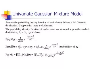
Gaussian Mixture-Sound Field Landmark Model (GM-SFLM) • An environmental sound field could be perceived by animals or human beings through the phase differences and magnitude ratio among sound receiving sensors. • The employed characteristics are usually called interaural time difference (ITD) and interaural level difference (ILD). Both ITD and IID represent meaningful physical quantities for a sound field perception. • The proposed GM-SFLM at each location is defined as the linear combination of the phase difference GMM and the magnitude ratio GMM . where and are the weighting factors, and are the phase difference and magnitude ratio GMM relatively.
Experimental Condition • The experiment was conducted by utilizing two microphones in an environment. • The spacing of two microphones is chosen as 10 cm. • There are 12 location blocks defined in the experiment. • Considering the size of the eRobot, the radius of the each location blocks is selected as 20 cm. The environment is complexly and it contains a partition room.
Experimental Condition • The experiment was performed in three different SNR conditionsThe SNR ranges of the three different cases are listed in the left Table. • The received signals were sampled at 8 KHz, and the window for STFT (Short Time Fourier Transform) contained 256 zero padding samples and 32ms speech signals, totaling 512 samples. The processed frame and the overlapping condition is shown in the left Figure. The SNR ranges of the three different conditions A processed frame and overlapping condition
Experimental Result Experimental result in condition one using GM-SFLM Experimental result in condition two using GM-SFLM Experimental result in condition three using GM-SFLM
Conclusion and Future Work • This work proves that the proposed method can capture the sound field characteristic to achieve a very high localization correct rate in noisy indoor environments. • The accurate and robust experimental results indicate a promising direction of using the sound as a mean of localization where the devices are relatively inexpensive. • However, several issues can be explored further, such as the relation of the proposed model to the acoustic scattering theory and 3D landmarks. These areas will be the work of continuing research of the authors.