Download
1 / 100
1k likes | 1.15k Vues
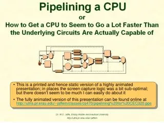
This is a printed and hence static version of a highly animated presentation; in places the screen capture logic was a bit sub-optimal; but there doesn’t seem to be much I can easily do about it

E N D
This is a printed and hence static version of a highly animated presentation; in places the screen capture logic was a bit sub-optimal; but there doesn’t seem to be much I can easily do about it • The fully animated version of this presentation can be found online at http://ultra.pr.erau.edu/~jaffem/classes/cs470/pipelining%20for%20CEC320.pps
Two multiplexers, under control of the opcode bits IR0..5, select which two of the four possible input sources are actually sent to the ALU • The upper ALUinput multiplexer selects either NPC or register A as one input, depending on whether or not the instruction is a branch or jump – for which a target address must be calculated based on the value of the NPC, which contains the address of the current instruction being executed • The lower ALUinput multiplexer controls whether register B or an immediate operand is sent to the other ALU input port, depending on whether or not the opcode IR0..5 designates an R-type instruction
IR0..5 and IR21..31 together specify the arithmetic or logical operation to be performed by the ALU — although only an R-type instruction actually needs to look at IR21..31
We get two outputs from the ALU: • The result of the specified operation is placed in ALUoutput • The condition register is set to either true or false; it’s used later, during writeback, to control whether a conditional branch is actually taken, e.g., “branch if non-zero”, based on the comparison the ALU just performed
During write back, the instruction type determines whether it is the LMD or the ALUoutput that is written into some general purpose register • An R-type or any I-type instruction other than a Load selects ALUoutput • A Load instruction selects the LMDA J-type doesn’t write back into the general purpose register set at all (only to the PC, coming right up ;-)
The specific register to be written to, if any, is designated by the destination register bits from the IR, e.g., the “3” in R3=R5-R1, which is found in IR11..15 for an I-type instruction or IR16..20 for an R-type, the instruction type being obtained from IR0..5
At the start of a cycle, all the latches are gated out onto data and control lines to setup all subsequent processing for that cycle
Also as before, the target register for the write back is determined by bit fields within the instruction; but note that it is the instruction in the write back stage, not the register fetch stage, that we want to control this operation, i.e., MEM/WB.IR controls the destination of the write back, not IF/ID.IR