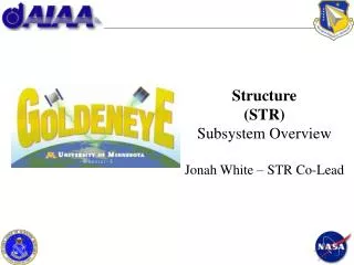
Structure (STR) Subsystem Overview Jonah White – STR Co-Lead
210 likes | 436 Vues
Structure (STR) Subsystem Overview Jonah White – STR Co-Lead. Structure Overview. Battery Box. Main Satellite Structure Functions Provide housing for all components Protect sensitive components from harmful launch/space conditions Electrically conductive to prevent plasma charging

Structure (STR) Subsystem Overview Jonah White – STR Co-Lead
E N D
Presentation Transcript
Structure Overview Battery Box • Main Satellite Structure Functions • Provide housing for all components • Protect sensitive components from harmful launch/space conditions • Electrically conductive to prevent plasma charging • Component Box Functions • Secures electrical components to main structure • Provides electrical magnetic interference (EMI) containment • Allows for better thermal control Component Boxes
Design Strategy • Make sure strategic requirements are fulfilled first • Static envelope (60 x 60 x 50 cm) • Fundamental frequency (greater than 100 Hz) • 20 g’s loading • C.G. (0.635 cm from centerline) • Mass limit (50 Kg) • Machine-ability • All parts can be machined • Advice from experienced machinists • Keep it simple!!! • Ease of assembly (~30 min for prototype) • Structural design is not the mission • Use NASA preferred parts if possible • Stick to what has been proven
Satellite Structure GPS Direct Signal Antennas Solar Panels Lightband Interface High Gain Antenna
Satellite Side Panel • Each Side Panel Consists Of • Aluminum panel with isogrid pattern • 11 machined brackets • Attached with #10 socket cap screws • Torque coil mounts • Attached with #8 socket cap screws Torque Coil
Satellite Side Panel • Assembly • Brackets tapped • Locking helicoils used for back-out prevention • Torque coil mounts attached using lock nuts • All pieces assembled to side panel before panel attached to main structure
Satellite Side Panel • Side Panels • Machined aluminum 6061-T6 • 0.635 cm thick (1/4 inch) • Alodined • Isogrid pattern • NASA-CR-124075, Rev. A, Isogrid Design Handbook • Use 60˚ equilateral triangles • 0.2 cm minimum triangle side thickness • Nodes no more than 7 cm apart • Rounds at all corners • #10 screw holes tapped to incorporate brackets and solar panels • #8 screw holes to attach component boxes
Satellite Bracket • Brackets • Machined aluminum 6061-T6 • 90˚ angle • 0.32 cm (~1/8 inch) round • #10 screw holes tapped thru (1.5 x diameter of screw) • JSC 23642, Rev. D, JSC Fastener Integrity Testing Program • Locking helicoils and spring lock washers for backout prevention
Torque Coil Mounts • Torque Coil Mounts • Machined aluminum 6061-T6 • 2 piece design • Assembled with #8 button head socket cap screws • Faces are 0.3 cm thick (~1/8in)
Satellite Top Panel • Satellite Top Panel Consists of • Aluminum panel with isogrid pattern • Torque coil • Attached with #8 socket cap screws • Battery component box • Attached with #8 socket cap screws
Satellite Top Panel • Top Panel Consists of • Machined aluminum 6061-T6 • 0.635 cm thick (1/4 inch) • Alodined • Isogrid pattern • #10 screw holes tapped to incorporate brackets and attach solar panels • #8 screw holes to attach battery box
Satellite Bottom Panel • Bottom Panel • Machined aluminum 6061-T6 • 0.635 cm thick (1/4 inch) • Alodined • Minimal isogriding • Hole cut-out to accommodate high gain antenna mounting • Lightband interface • #10 screw holes tapped to incorporate brackets
Battery Box • Battery Box • 3 piece box machined aluminum design • Stand-offs to accommodate solar panel screws • #8 screws for assembly • Utilize viton gasket for EMI containment
Battery Box • Machined aluminum • 0.3 cm (1/8 inch) thick • Coatings • Outside box alodined • Inside box anodized
Component Boxes • Component Boxes • 3 piece box design • Machined aluminum • Stand-offs to accommodate solar panel screws • #8 screws for assembly • Utilize viton gasket for EMI containment • Alodined
Mass Breakdown • Total mass • 38.8 Kg