From Use Cases to Implementation: Mapping Requirements to Design and Code
This document explores the guidance from requirements to design and coding in software development. It emphasizes the importance of clearly defined use cases, the challenges posed by the orthogonality problem in relating requirements to actual code implementation, and the need for system architecture to navigate complexity. It also discusses the "4+1" view model of architecture, which includes logical, implementation, process, and deployment views to address different stakeholder perspectives, ultimately aiding in effective system design and understanding.

From Use Cases to Implementation: Mapping Requirements to Design and Code
E N D
Presentation Transcript
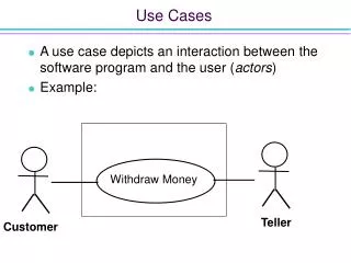
Mapping Requirements Directly to Design and Code • For many, if not most, of our requirements it is relatively easy to follow them into design and then into code. E.g., “Only users with a valid password can access the system.” • For these requirements it is also easy to use the statement of the requirement as a basis for testing. • For some requirements, however, this is not quite so easy. E.g., “The system shall provide ½ second response time for all trivial user requests.”
Orthogonality between Requirements and Design • The form of the requirements and the form of the design and implementation are different. • There is no one-to-one mapping that makes implementation and validation easier.
The Orthogonality Problem • Requirements speak about real-world items, but code speaks about stacks, queues, and algorithms. These are different languages. • Certain requirements, e.g., performance, have little to do with the logical structure of the code but lots to do with the process structure, or how the various pieces of the code interact, how fast a particular piece of code runs, how often we get interrupted in a given module, etc.
The Orthogonality Problem (Cont’d) • Other functional requirements require that a number of system elements interact to achieve the functionality. The implementation might be distributed throughout the code. • Good system design is not driven by the ease of mapping requirements into design but by other factors, such as, optimizing the use of scarce resources, reusing architectural patterns, designs or code, or utilizing purchased components.
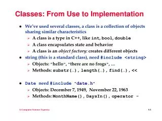
Object Orientation • Object oriented technology has helped to reduce the magnitude of the orthogonality problem through the use of abstraction, information hiding, inheritance, etc. • OO technology encourages designs which match the real world descriptions of the problem. • However, if carried too far a functionally oriented design might result rather than one that is object oriented.
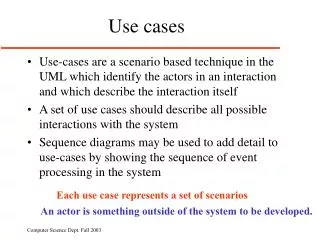
The Use Case as a Requirement • If the granularity of requirements is too small it may be difficult to look at system behavior as a whole to see that it does all the right things in the right order. • Properly written use cases which provide sequences of actions between the system and the user help with this problem. • In this way use cases help with the design process.
Modeling Software Systems • Today’s nontrivial software systems are extraordinarily complex undertakings. • To deal with the complexity, a useful technique is to abstract the system into a simple model to allow us to think about the system without having to deal with the details. • Many different aspects of a system can be modeled. Each contributes to our understanding of one aspect and taken together they allow us to consider the system architecture as a whole.
The Architecture of Software Systems • According to Shaw and Garlan [1996], software architecture involves the Description of elements from which systems are built, interactions amongst those elements, patterns that guide their composition, and constraints on those patterns. • We use architecture to help us: • Understand what the system does • Understand how the system works • Think and work on pieces of the system • Extend the system • Reuse part(s) of the system to build another one
The Architecture of Software Systems (Cont’d) • Architecture is the tool by which decisions are made about what and how the system will be built. • Dominant architectures, used for previous similar problems, can help kick start the process. • Different groups of stakeholders may require different views of the architectural model showing their different perspectives.
The “4+1” View of Architecture Programmer Software management End User Functionality Logical View Implementation View Use-case View Designers/Testers Behavior Process View Deployment View System Engineering System topology Delivery, installation Communication System Integrators Performance Scalability Throughput
The “4+1” View of Architecture (Cont’d) • The logical view addresses the functionality of the system. It represents the logical structure of the system in terms of subsystems and classes. • The implementation view describes a static view of the bits and pieces that are relevant to the implementation of the system: source code, libraries, object classes, etc.
The “4+1” View of Architecture (Cont’d) • The process view(s) describe operations of the system and are particularly useful for systems which have parallel tasks, interfaces with other systems, etc. • The deployment view allocates the implementation elements to the supporting infrastructure, such as operating systems and computing platforms
The “4+1” View of Architecture (Cont’d) • The use-case view presents key use cases of the use-case model, drives the design, and ties all the various views of the architecture together
Realizing Use Cases in the Design Model • Use cases are realized via collaborations, which are societies of classes, interfaces, subsystems, or other elements that cooperate to achieve some behavior. • It is within the collaborations that you see the systematic and aggregate behavioral aspects of the system.
Realizing Use Cases in the Design Model Use-case Model Design Model <<trace>> Use case Collaboration Participating classes
Structural and Behavioral Aspects of Collaborations • Two aspects of Collaborations • Structural – specifies the static structure of the system (the classes, elements, interfaces, and subsystems) • Behavioral – specifies the dynamics of how the elements of the system work together. • Class diagrams can represent the structural aspects and sequence diagrams can model the behavioral aspects.
Using Collaborations to Realize Sets of Individual Requirements • Even if the requirements are not expressed as use cases we can use this technique to create a map between sets of requirements and collaborations. • Design elements that support nonfunctional requirements, such as safety or performance, can also be modeled in this way.
Model of Requirements Implementation as a Collaboration • Requirements • - The clocks shall . . . • Every 24 hours . . . • - Synchronization occurs . . . Design Model Sync Clock <<trace>> Collaboration Participating classes