Use Cases: Traditional Methods for Expressing Functionality in Early Software Development
This chapter explores traditional methodologies for expressing system functionality throughout the early stages of software development. It covers key techniques such as Requirements Specifications, Data Flow Diagrams (DFDs), and Entity-Relationship Diagrams (ERDs) that have been vital in capturing and communicating system requirements. While DFDs provide dynamic views of data flows and interactions, ERDs focus on static data relationships. Additionally, we discuss the role of prototypes and the importance of understanding user interactions to clarify system requirements effectively.


Use Cases: Traditional Methods for Expressing Functionality in Early Software Development
E N D
Presentation Transcript
Moving to Use Cases Chapter 2 – Part 1
Traditional Modes of Expressing Functionality to Users Early in Lifecycle: • Requirements Specifications • Normally in terms of ‘lists’ • Data Flow Diagrams (DFDs) • Entity-Relationship Diagrams (ERDs) • Prototypes
Discussing these technologies • Requirements Lists • A comprehensive list of functions • An itemization • Implies functions can be extracted and implemented. • DFDs – show data flows; interacting processes. • Contains Processes, Data flows, data stores. • Data flows from process to process stopping at a data store. • A dynamic view of the system • Shows what happens INSIDE the system. – no algorithms… • External entities lie outside the system boundary and trigger the system. • Typically contain a lot of detail and many levels… • Still useful in design – especially with non-object-oriented systems.
Data Flow Diagram Conventions Data Flow Diagram Conventions Emphasis in DFDs is on v Emphasis in DFDs is on v Processing Processing Process Process Box v Process Box v Transform Inputs into Outputs w Transform Inputs into Outputs w Performed by People, Computers... w Performed by People, Computers... w External / Internal Entity v External / Internal Entity v External Entity Define Boundary of System w Define Boundary of System w Provide Net Inputs and/or Receive w Provide Net Inputs and/or Receive w Net Outputs from System Net Outputs from System 1
Step 3 – Middle Level – Identification of Transaction Flow - Form letter: Membership Welcome or Denial 1.1 Form 40: Transcribed Special Order Mail Subscription Process Potential Card & Order Form Subscription Member Current Member Status Transaction 1.2 Member Form Ltr : Notice of Pending Bonus Updates dbase IV Member Mail: Mbrshp Renewal Slip Process Club Membership Member Renewal Mail: Renewal Welcome Ltr Transaction Form Ltr : Membership Member Updates 1.3 Cancellation Confirmation Process Mail/Phone: Membership Membership Form 25: Outstanding Cancellation (letter) A/R Credit Notice Cancellation Department Transaction 4 4
Discussing these technologies • Entity-relation diagrams • A static view of data and data relationships… • Show details of entities (attributes, relationships) • Show how data is stored in application • Used a lot for information engineering approaches. • Not dynamic and require DFDs for the dynamics. • Sometimes the differences between static and dynamic views of system are confusing to users. • Still good for creating logical data models after requirements have been gathered and for creating your database and your fully-attributed list. Used extensively in database modeling and design. • Provide little meaning / utility to the user.
Entity Relationship Diagrams (continued) Entity Relationship Diagrams (continued) ERDs REPRESENT ALL DATA THAT ARE v INPUT, STORED, TRANSFORMED, AND PRODUCED IN A MANNER THAT IS INDEPENDENT OF THE PROCESSING THAT TRANSFORMS THEM... cardinality / modality Manufacturer builds Automobile CSX 9
Entity Relationship Diagrams (continued) Entity Relationship Diagrams (continued) Oftentimes specific attribute values may be shown in tables |< ------------------- ATTRIBUTES (FIELDS / MEMBERS) ---------------- > |< ------------------- ATTRIBUTES (FIELDS / MEMBERS) ---------------- > MAKE MODEL ID# BODY TYPE COLOR REFERENCE E MAKE MODEL ID# BODY TYPE COLOR REFERENC E FORD MUSTANG 1234 2 - DOOR RED RFR FORD MUSTANG 1234 2 - DOOR RED RFR PLYM VOYAGER 2345 4 - DOOR WHITE CAR PLYM VOYAGER 2345 4 - DOOR WHITE CAR HONDA LX 4455 4 - DOOR GREEN JDR HONDA LX 4455 4 - DOOR GREEN JDR PONT GRAN AM 8899 2 - DOOR RED ETS PONT GRAN AM 8899 2 - DOOR RED ETS CSX 10
Discussing these technologies • Prototypes • Concentrate on user interface • Omit almost all of business rules and background coding. • Executives have a hard time realizing that what they see is only façade… • Should not be used as a main requirements tool. • Good for ascertaining the user interface, though
Discussion: Summary of these Technologies • Requirements Specs are rarely used once application is produced. (Discuss…) • DFDs and ERDs are useful for moving into programming and into database design • Mean little to users • Prototypes obscure the real requirements and seem to emphasize the interface at the expense of the real application’s functionality. • DFDs, ERDs, and prototypes include both ‘whats’ and ‘hows’ in their perspectives – confuses users, and this is not advisable.
Interactions with the User • Need to emphasize capturing the requirements of the system from the users’ perspective. • Users view systems as black boxes (explain) • Requirements emphasizing black box approach – much more meaningful to users. • Implies: it’s all about interactions. • Use Cases are tools that should be used to show the ‘What’ of a system exclusively!
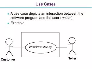
Hello World • Basic Hello World Use Case is a ‘system context’ use case. Covered later…(Façade Use Case) • Use Case – two parts • Use Case Diagram • Use Case Description (narrative) • Diagram presents overview of important interactions • Can include in Rational Rose • Narrative presents the details of the interactions • Can include Word Descriptions in Rational Rose via Requisite Pro • Use Cases have actors (entities outside the system) interacting with Use Cases. • A Use Case represents requirements often stated in verb-object format, like Sell Property. Stories of user interactions with system.
Typical Use Case for Selling Property – Main Use Case Diagram
Use Case Diagrams • Used to visually show system interactions and to capture the scope. • Easily drawn – with accompanying documentation (specification) using a software tool, such as Rational Rose. • The Use Case itself (narrative) needs to be ‘at the same level’ as the diagram and present much more detail than the diagram. (functionality)
Sample Use Case Narrative Discuss numbering, column formats, etc.
Use Cases • Textbook uses a different format. • Can readily created these narratives using ‘Tables’ in Word and linking them into your Use Cases by double clicking on a specific Use Case symbol in a Use Case Diagram, selecting “Files” tab, right clicking (to show short cut menu) and selecting Insert File to link to your Word file via browsing. • But with Requisite Pro, can link Word documents directly into Rose.
Use Cases (more) • Book uses a Filled Use Case (includes the flow of events) – normally done during elaboration • In Inception, Façade Use Cases are helpful • (chapter 5 in Use Case textbook) • Note the elements constituting a Use Case – eventually – name, iteration, actors, description / flow of events, alternative paths, exception points, triggers, assumptions, pre- and post conditions, related business rules (for traceability), an author and a date – for version control. • Pages 21 – 38 in the Visually Modeling textbook covers how to use rational rose and use case modeling in very explicit detail!
Unified Modeling Language • Recall: the UML is a ‘notation’ – a way to document system specifications and interactions. • UML is not dependent upon any specific methodology (process). You need a process WITH this notation!! • UML does require that the system has object-oriented components. • Use cases themselves can be used for systems that are NOT based on object orientation. • The UML has nine diagrams that provide different necessary views of the system. • Diagrams are dependent upon each other. • Changes to one often means changes to another diagram.
Use Case Diagram • Use Case diagrams and descriptions are the drivers for the rest of the diagrams. • Need to be done first; Written in language of the user! • Use Cases are text descriptions of interactions between some actors and the system. • Use Case Diagrams are graphical representations between actors and use cases. • Can have relationships between use cases themselves (includes; extends; others….) • “Have the simplicity to represent a computer system’s essence, and yet they have the power to drive the entire methodology…”