Download
1 / 16
160 likes | 321 Vues
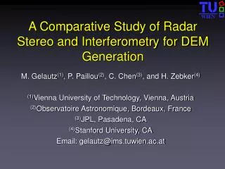
Investigations of cross-channel interference on a stereo SuperDARN radar. A. McDonald (1), J . Devlin (2 ). (1) Department of Physics, La Trobe University, Victoria, Australia (2) Department of Electronic Engineering, La Trobe University, Victoria, Australia. Abstract.

E N D
Investigations of cross-channel interference on a stereo SuperDARN radar A. McDonald (1), J. Devlin (2). (1) Department of Physics, La Trobe University, Victoria, Australia (2) Department of Electronic Engineering, La Trobe University, Victoria, Australia
Abstract Interference between channels while operating in two channel 'stereo' mode is investigated for the TIGER UnwinSuperDARN radar. A discretionary mode was run in which channel A cycles sequentially over a number of pre-set frequencies while channel B remains fixed. It was found that for certain values of the channel A and channel B frequencies and for certain beams, the number of echoes received on the fixed frequency channel B depends strongly on the frequency on channel A at the time. For a stereo radar to be operating properly there should be no such correlation effects between channels. This cross-channel interference is observed not to depend on ionospheric conditions, only on the particular frequencies used. Spurious channel B echoes resulting from cross-channel interference exhibit low velocities, an absence of low spectral widths and occur at intermediate ranges. Results of a number of tests are presented providing insight into this issue currently under investigation.
Sequential Frequency Mode • For each 1-minute scan over all 16 beams, channel A is fixed at one of five pre-set frequencies while channel B scans in a synchronous manner at a single fixed frequency. Channel A cycles through fixed frequencies 9050,10190,12190,14390 and 16350 kHz sequentially for 1 minute each while Channel B is fixed at 10390 kHz.
We analysed channel B (fixed frequency) echo occurrence with regards to the channel A frequency in operation at the time, to check for cross-channel interference. Figure 1). Spurious channel B echoes on a number of beams when channel A is 16350 kHz. No spurious channel B echoes.
As a reference we calculated the expected value and standard deviation for • randomly binning channel B echoes, into 5 frequency bins. • If there is no correlation between channel B echo occurrence and channel A frequency, the channel B echoes for each beam should be evenly distributed over the 5 channel A frequencies. • This means the 5 occurrence distributions should coincide. • The Problem • In Figure 1), clearly a much greater number of channel B echoes is detected when channel A is scanning at 16350 kHz, particularly on beams 11, 14 and 15. • This effect is not seen all the time, depending critically on the channel B (fixed) frequency chosen, and on the channel A frequency. The details of this frequency dependence is still unclear.
The effect does not seem to depend on ionospheric conditions. • For the original sequential frequency mode (channel B=10390 kHz and • channel A=[9050,10190,12190,14390,16350]), the same effects are reproduced • on all 20 days analysed over a three-month period, over widely varying • ionospheric conditions.
The main focus has been on 16350 kHz • The generation of spurious echoes is clearly frequency dependent. • Analysis of interference as channel A frequency approaches 16350 kHz, shows a progressive growth in spurious channel B echoes.
The effect is not seen on channel A. • Running the sequential frequency mode with • channels switched and analysing channel A echo • occurrences (Figure 2) shows no spurious spikes. • No dependence of channel A echo occurrence • on channel B frequencies is observed. • In addition, there are no spikes in channel A echo occurrences at the same time and on the same beams as the spurious channel B echoes are occurring. • (in Figure 1 for example) Figure 2.
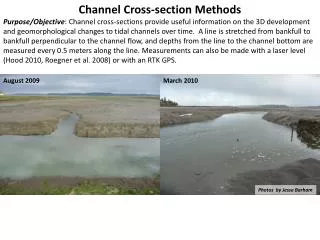
Characteristics of spurious channel B echoes Range Spectral Width
Velocity Excluding velocities < | 100 m/s |
Frequency bands vs fixed frequencies • In the original mode, the selected frequencies were rigidly fixed, • by-passing the clear frequency search in the radar operating system. • The effect on cross-channel interference of re-instating frequency bands of • non-zero width was also investigated.
Data from other Stereo SuperDARN Radars • The CUTLASS Pykkvibaer radar is very similar to TIGER Unwin, with close to • identical hardware and software. • In this mode, Milan et. al. use channel A as the fixed frequency and • Channel B for the sequential frequencies.
Conclusions • The channel B echo count is sometimes unreliable, exhibiting a dependence on the frequency channel A is scanning on. • Channel A echo counts are reliable. • The interference on channel B is a hardware issue. The pulse sequence for a stereo radar is not symmetric between channels, with channel A always leading. A maintenance trip to the radar is planned to perform hardware tests. • The characteristics of the spurious channel B echoes are: • low velocities, with magnitude < 100 m/s • an absence of low spectral widths • intermediate ranges 1000 – 2000 km. Recommendations • When using stereo modes, routinely check for cross-channel interference. • Use frequency bands with non-zero width of around 500 kHz.