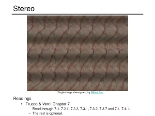
Stereo Vision Processing and Image Rectification for Photogrammetric Surveys
This document discusses the methodology for rectifying and plotting single images using stereo vision techniques, focusing on interior and relative orientation processes. It outlines the use of control points and known distances between point pairs to achieve overlay of plotted data while maintaining perspective fidelity typical of digital cameras. It details the digitization and calibration involved in a photogrammetric survey of Augustus' Temple in Ankara, employing specific camera parameters and hardware devices. The results and accuracy achieved in control point determination are presented, showcasing the effectiveness of the stereo vision methodology in architectural surveys.

Stereo Vision Processing and Image Rectification for Photogrammetric Surveys
E N D
Presentation Transcript
RECTIFICATION AND PLOTTING OF SINGLE IMAGE • THE ORIENTATIÓN CAN BE ACHIEVED: • BY CONTROL POINTS • BY KNOWN DISTANCES BETWEEN COUPLES OF POINTS WE CAN OBSERVE THAT THE PLOTTING OVERLAYS THE IMAGE MANTAINING THE PERSPECTIVE
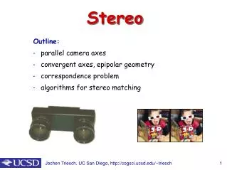
PHOTOGRAPH OF THE DIGITAL CAMERA • Interior Orientation • DIGITAL CAMERA: THE CORNERS OF THE IMAGE • METRIC OR SEMIMETRIC CAMERA: THE FIDUCIAL MARKS MARK IMPRESSED ON THE PLATE BY THE RESEAU MARKING THE CORNER PHOTOGRAPH TAKEN WITH A SEMI-METRIC CAMERA, FORMAT 6 X 6 CM2
IN THIS SYSTEM THE Y AXIS IS NOT PERPENDICULAR TO THE FACADE Y AXIS IS PERPENDICULAR TO THE FACADE. WE GOT THE SUITABLE DATUM • For facade plotting, in comparison to the aerial images, we will change the coordinate (y) with the elevation of the points (z). We will keep XZ plane parallel to the working plane. • In case that it is not as such: Rotate the system about vertical axis to make XZ plane parallel to the façade
the marked points define two vectors with known lenght: 100-101 (18.19 MT) Y 102-103 (14.67 MT).
Marrakesh – Bab Agnau (courtesy of School of Arabic Studies)
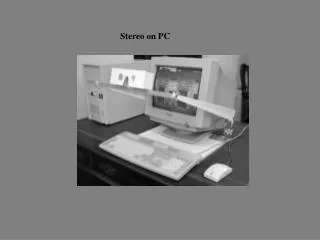
DIGITAL PHOTOGRAMMETRICWORKSTATION STEREOMETRIC PRO by Galileo Siscam. 4)
HARDWARE DEVICE FOR STEREO VISION PLOTTING WITH STEREOMETRIC PRO AN ARCHITECTURAL EXAMPLE: THE AUGUSTUS’ TEMPLE IN ANKARA TEST ON AERIAL TRIANGULATION CONSTRUCTION OF A DEM WITH DEM MANAGER FEATURES : EVALUATUION AND CONCLUSIONS Topics:
HARDWARE FOR STEREO- VISION Transmitter to the glass Control unit NuVISION 60GX Track-Ball Mouse CRYSTAL EYES
PHOTOGRAMMETRIC SURVEY • stereo coverage • scanning at suitable resolution GEODETIC SURVEY • Suitable quantity and distribution • Accuracy CALIBRATIONCERTIFICATE • Focal distance • Coordinates of fiducial marks • Distortion PLOTTING WITH STEREOMETRIC PRO – Galileo Siscam INPUT DATA DIGITIZEDIMAGES CONTROL NETWORK CAMERAPARAMETERS
Features • total Station Topcon GTP 1002 • 11 theodolitestazions • 175 control points • Adjustment Software : RETE • plan-altimetric accuracy ± 0.5 cm CONTROL NETWORK August-September 2000
Features • Rollei 6008 semi-metric 6X6 • Focal length: 40,37 mm • 52 images • average scale 1:200 \ 1:300 AUGUSTUS TEMPLE IN ANKARA PHOTOGRAMMETRIC SURVEY August-September 2000
Project set-up: AUGUSTUS’TEMPLE IN ANKARA • ACCURACY OF THE CONTROL POINTS ±1 CM • IMMAGE SCANNING AT 1200 DPI (Dot Per Inch) 52 IMAGES AVERAGE SCALE 1:200-1:300 43 PLOTTED MODELS PIXEL size 21 Micron INPUT DATA