Understanding Depth Perception: Cues and Mechanisms in Human Vision
This article explores the various depth cues that allow humans to perceive depth in their visual environment. It discusses both binocular and monocular cues, including convergence, binocular parallax, and motion parallax, as well as monocular cues like retinal image size, linear perspective, texture gradient, overlapping, aerial haze, and shades/shadows. Additionally, the principles of stereo vision and the importance of triangulation in depth perception are addressed. The interplay of these cues plays a crucial role in how we interpret distances and dimensions in everyday life.


Understanding Depth Perception: Cues and Mechanisms in Human Vision
E N D
Presentation Transcript
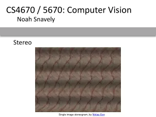
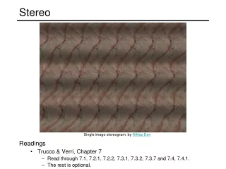
Stereo CSE P 576 Larry Zitnick (larryz@microsoft.com) Many slides courtesy of Steve Seitz
What do humans use as depth cues? Motion Convergence When watching an object close to us, our eyes point slightly inward. This difference in the direction of the eyes is called convergence. This depth cue is effective only on short distances (less than 10 meters). Binocular Parallax As our eyes see the world from slightly different locations, the images sensed by the eyes are slightly different. This difference in the sensed images is called binocular parallax. Human visual system is very sensitive to these differences, and binocular parallax is the most important depth cue for medium viewing distances. The sense of depth can be achieved using binocular parallax even if all other depth cues are removed. Monocular Movement Parallax If we close one of our eyes, we can perceive depth by moving our head. This happens because human visual system can extract depth information in two similar images sensed after each other, in the same way it can combine two images from different eyes. Focus Accommodation Accommodation is the tension of the muscle that changes the focal length of the lens of eye. Thus it brings into focus objects at different distances. This depth cue is quite weak, and it is effective only at short viewing distances (less than 2 meters) and with other cues. Marko Teittinenhttp://www.hitl.washington.edu/scivw/EVE/III.A.1.c.DepthCues.html
What do humans use as depth cues? Image cues Retinal Image Size When the real size of the object is known, our brain compares the sensed size of the object to this real size, and thus acquires information about the distance of the object. Linear Perspective When looking down a straight level road we see the parallel sides of the road meet in the horizon. This effect is often visible in photos and it is an important depth cue. It is called linear perspective. Texture Gradient The closer we are to an object the more detail we can see of its surface texture. So objects with smooth textures are usually interpreted being farther away. This is especially true if the surface texture spans all the distance from near to far. Overlapping When objects block each other out of our sight, we know that the object that blocks the other one is closer to us. The object whose outline pattern looks more continuous is felt to lie closer. Aerial Haze The mountains in the horizon look always slightly bluish or hazy. The reason for this are small water and dust particles in the air between the eye and the mountains. The farther the mountains, the hazier they look. Shades and Shadows When we know the location of a light source and see objects casting shadows on other objects, we learn that the object shadowing the other is closer to the light source. As most illumination comes downward we tend to resolve ambiguities using this information. The three dimensional looking computer user interfaces are a nice example on this. Also, bright objects seem to be closer to the observer than dark ones. Jonathan Chiu Marko Teittinenhttp://www.hitl.washington.edu/scivw/EVE/III.A.1.c.DepthCues.html
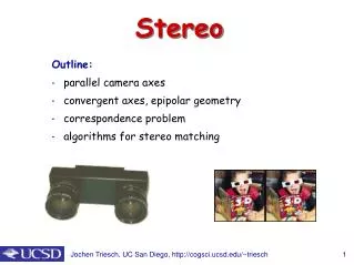
Stereo scene point image plane optical center
Stereo • Basic Principle: Triangulation • Gives reconstruction as intersection of two rays • Requires • camera pose (calibration) • point correspondence
epipolar line epipolar line epipolar plane Stereo correspondence • Determine Pixel Correspondence • Pairs of points that correspond to same scene point • Epipolar Constraint • Reduces correspondence problem to 1D search along conjugateepipolar lines • Java demo: http://www.ai.sri.com/~luong/research/Meta3DViewer/EpipolarGeo.html
l l’ p p’ Fundamental matrix • Let p be a point in left image, p’ in right image • Epipolar relation • p maps to epipolar line l’ • p’ maps to epipolar line l • Epipolar mapping described by a 3x3 matrix F • It follows that
Fundamental matrix • This matrix F is called • the “Essential Matrix” • when image intrinsic parameters are known • the “Fundamental Matrix” • more generally (uncalibrated case) • Can solve for F from point correspondences • Each (p, p’) pair gives one linear equation in entries of F • 8 points give enough to solve for F (8-point algorithm) • see Marc Pollefey’s notes for a nice tutorial
Stereo image rectification • reproject image planes onto a common • plane parallel to the line between optical centers • pixel motion is horizontal after this transformation • two homographies (3x3 transform), one for each input image reprojection • C. Loop and Z. Zhang. Computing Rectifying Homographies for Stereo Vision. IEEE Conf. Computer Vision and Pattern Recognition, 1999.
Example Unrectified Rectified
X z x x’ f f baseline C C’ Depth from disparity
Stereo matching algorithms • Match Pixels in Conjugate Epipolar Lines • Assume brightness constancy • This is a tough problem • Numerous approaches • A good survey and evaluation: http://www.middlebury.edu/stereo/
For each epipolar line For each pixel in the left image • Improvement: match windows • This should look familar... Your basic stereo algorithm • compare with every pixel on same epipolar line in right image • pick pixel with minimum match cost
Stereo as energy minimization • Find disparities d that minimize an energy function • Simple pixel / window matching = SSD distance between windows I(x, y) and J(x, y + d(x,y))
Stereo as energy minimization I(x, y) J(x, y) y = 141 d x C(x, y, d); the disparity space image (DSI)
Stereo as energy minimization y = 141 d x Simple pixel / window matching: choose the minimum of each column in the DSI independently:
Matching windows SSD SAD NCC Ground truth http://siddhantahuja.wordpress.com/category/stereo-vision/
More window techniques Bilateral filtering Adaptive weighting K.-J. Yoon and I.-S. Kweon. Adaptive support-weight approach for correspondence search. PAMI 28(4):650-656, 2006 Ground truth Yoon and Kweon
W = 3 W = 20 Window size • Smaller window • Larger window Effect of window size • Better results with adaptive window • T. Kanade and M. Okutomi,A Stereo Matching Algorithm with an Adaptive Window: Theory and Experiment,, Proc. International Conference on Robotics and Automation, 1991. • D. Scharstein and R. Szeliski. Stereo matching with nonlinear diffusion. International Journal of Computer Vision, 28(2):155-174, July 1998
Stereo as energy minimization • What defines a good stereo correspondence? • Match quality • Want each pixel to find a good match in the other image • Smoothness • If two pixels are adjacent, they should (usually) move about the same amount
Stereo as energy minimization • Better objective function { { smoothness cost match cost • Want each pixel to find a good match in the other image • Adjacent pixels should (usually) move about the same amount
Stereo as energy minimization match cost: smoothness cost: : set of neighboring pixels 4-connected neighborhood 8-connected neighborhood
Smoothness cost L1 distance “Potts model”
Dynamic programming • Can minimize this independently per scanline using dynamic programming (DP) : minimum cost of solution such that d(x,y) = d
edge weight d3 d2 d1 edge weight Energy minimization via graph cuts Labels (disparities)
d3 d2 d1 Energy minimization via graph cuts • Graph Cut • Delete enough edges so that • each pixel is connected to exactly one label node • Cost of a cut: sum of deleted edge weights • Finding min cost cut equivalent to finding global minimum of energy function
Computing a multiway cut • With 2 labels: classical min-cut problem • Solvable by standard flow algorithms • polynomial time in theory, nearly linear in practice • More than 2 terminals: NP-hard [Dahlhaus et al., STOC ‘92] • Efficient approximation algorithms exist • Boykov, Veksler and Zabih, Fast Approximate Energy Minimization via Graph Cuts, ICCV 1999. • Within a factor of 2 of optimal • Computes local minimum in a strong sense • even very large moves will not improve the energy
Red-blue swap move Green expansion move Move examples Idea: convert multi-way cut into a sequence of binary cut problems Starting point
B A AB subgraph (run min-cut on this graph) The swap move algorithm 1. Start with an arbitrary labeling 2. Cycle through every label pair (A,B) in some order 2.1 Find the lowest E labeling within a single AB-swap 2.2 Go there if it’s lower E than the current labeling 3. If E did not decrease in the cycle, we’re done Otherwise, go to step 2 B A Original graph
Alpha-expansion Similar to swap move algorithm, except it’s one label vs. all others.
Other energy functions • Can optimize other functions (exactly or approximately) with graph cuts But many functions are much harder…
Markov Random Fields • Allows rich probabilistic models for images. • But built in a local, modular way. Learn local relationships, get global effects out. MRF slides courtesy of Antonio Torralba
Network joint probability 1 Õ Õ = Y F P ( x , y ) ( x , x ) ( x , y ) i j i i Z , i j i disparity Disparity-disparity compatibility function Images-disparity compatibility function images local observations neighboring disparity nodes
MESSAGES: Approximate sufficient statistics I. Belief Update (Message Product) II. Message Propagation (Convolution) Belief Propagation BELIEFS: Approximate posterior marginal distributions neighborhood of node i
For general graphs, loopy BP has excellent empirical performance in many applications • Recent theory provides some guarantees: • Statisical physics: variational method(Yedidia, Freeman, & Weiss) • BP as reparameterization: error bounds(Wainwright, Jaakkola, & Willsky) • Many others… Justifications for BP • Gives exact marginals for trees Optimal estimates Confidence measures
References on BP and GBP • J. Pearl, 1985 • classic • Y. Weiss, NIPS 1998 • Inspires application of BP to vision • W. Freeman et al learning low-level vision, IJCV 1999 • Applications in super-resolution, motion, shading/paint discrimination • H. Shum et al, ECCV 2002 • Application to stereo • M. Wainwright, T. Jaakkola, A. Willsky • Reparameterization version • J. Yedidia, AAAI 2000 • The clearest place to read about BP and GBP.
MRF results SSD V. Kolmogorov and R. Zabih. Computing visual correspondence with occlusions using graph cuts. ICCV 2001. Ground truth
Segmentation approaches L. Zitnick, S.B. Kang, M. Uyttendaele, S. Winder, and R. Szeliski. High-quality video view interpolation using a layered representation. SIGGRAPH 2004.
Real-time stereo • Used for robot navigation (and other tasks) • Several software-based real-time stereo techniques have been developed (most based on simple discrete search) • Nomad robot searches for meteorites in Antartica • http://www.frc.ri.cmu.edu/projects/meteorobot/index.html
Using more than two images Multi-View Stereo for Community Photo CollectionsM. Goesele, N. Snavely, B. Curless, H. Hoppe, S. SeitzProceedings of ICCV 2007,
Why does stereo fail? Fronto-Parallel Surfaces: Depth is constant within the region of local support
Why does stereo fail? Monotonic Ordering - Points along an epipolarscanline appear in the same order in both stereo images Occlusion – All points are visible in each image
Why does stereo fail? Image Brightness Constancy: Assuming Lambertian surfaces, the brightness of corresponding points in stereo images are the same.
Why does stereo fail? Match Uniqueness: For every point in one stereo image, there is at most one corresponding point in the other image.
Stereo reconstruction pipeline • Steps • Calibrate cameras • Rectify images • Compute disparity • Estimate depth • Camera calibration errors • Poor image resolution • Occlusions • Violations of brightness constancy (specular reflections) • Large motions • Low-contrast image regions What will cause errors?