Download
1 / 21
210 likes | 357 Vues
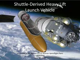
This presentation outlines the objectives and progress of a project aimed at designing a heavy lift cargo plane for the SAE Aero East competition. The aircraft must successfully take off from a 200-foot runway and land on a 400-foot runway while adhering to weight and dimensional constraints. The team focuses on aspects like induced drag, stability, and payload predictions. Detailed discussions cover wing structure fabrication, landing gear analysis, flight control systems, and updated budget plans for the project's next phase. Through rigorous testing and design iterations, the goal is to achieve optimal performance by April.

E N D
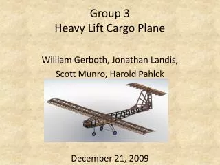
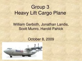
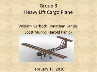
Group 3Heavy Lift Cargo Plane William Gerboth, Jonathan Landis, Scott Munro, Harold Pahlck February 18, 2010
Presentation Outline Project Objectives Q&A From Phase III Revised Payload Prediction Flight Controls Prototype Fabrication Plan Fabrication Schedule Updated Budget Plan for Phase V Nugget Chart
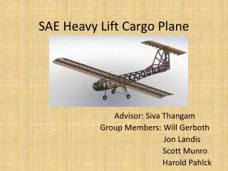
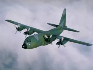
Project Objectives Design and build an airplane that meets the requirements of the SAE Aero East competition Plane must successfully take off from a runway of 200 feet and land on a runway 400 feet Constraints of 55 pounds total weight, and the combined height, length, and width of 200 inches Plane must make one complete 360° circuit of the field per attempt
Phase III Questions • How is Induced Drag accounted for? • Drag as a result of lift created by a finite wing • Induced drag coefficient is added to overall drag • Landing Gear Analysis • Used deflection to gain an understanding of the bending that can be expected during landing • Stability • The center of gravity is located in a neutral point • With increasing payloads the plane maintains a positive static margin
Phase III Questions (cont.) • Explanation of Graphs • Takeoff calculations done in excel • Using takeoff velocity, stall velocity, and ground roll distance • One Pound Force used in Analysis • Using a force of 15mph wind perpendicular to the tail creates a force of 1.3 pounds • Ease of Assembly and Manufacturing • Difference in thickness of trailing edge • Ability to make changes in internal workings
Revised Payload Prediction • Grass runway instead of concrete • Higher coefficient of rolling friction • Grass takeoff requires long takeoff distance, reducing payload that can be lifted in 200 ft. • Calculations showed reduction of 2 lbs’ • Expecting more reduction due to unforeseen factors such as terrain and length of grass
Flight Controls • 8 Servos Used • 1 servo per aileron and flap located in wing • 1 for each elevator located at rear of the fuselage • 1 for the throttle • 1 for the rudder and front wheel
Flight Control Sizing • Two approaches • Used largest value from following calculation and table
Fabrication – Wing Structure • Constructed using 38 ribs • Ribs cut using Eppler 423 template with a X-Acto knife • Ribs connected using a system of spars • One spar at the leading edge, one at 25% of the cord and five separate spars along the trailing edge • Flaps and ailerons will be attached to the trailing edge with hinges • Holes will be drilled for bolting to fuselage • Entire wing structure covered in Monokote using heat gun
Fabrication - Fuselage • Front cowl made of balsa • Firewall behind cowl made of plywood • Center section of fuselage constructed with a cargo opening, balsa walls, and plywood floor for structural rigidity • Supports added to the center section for rigidity and to allow mounting of the wing • Rear of fuselage built from ribs tapering in size • Fuselage covered in Monokote
Fabrication – Tail Plane • Two main components vertical and horizontal tail • Vertical tail cut from balsa wood • Rudder attached to rear with hinges • Horizontal tail made from 12 ribs cut from NACA 0012 template • Three spars will connect ribs • Vertical stabilizers will be connected to the rear using hinges
Fabrication – Landing Gear • Salvaged from previous years • Front Landing Gear – commercially purchased strut with spring to absorb impact • Rear Landing Gear – Aluminum stamped into horseshoe shape • Steel cable attached between two rear wheels • Rear landing gear bolted to fuselage • Front landing gear attached to allow rotation for steering
Plan for Phase V • Parts have been ordered • Fabricate aluminum templates to cut the balsa wood ribs • Use materials currently in the storeroom • Contact RC pilot to test model when finished • Complete aircraft by beginning of April
ME 424 Phase IV Nugget Chart– Performance Testing & Design Improvement Title: Heavy Cargo Lift Plane Team Members: William Gerboth, Scott Munro, Jonathan Landis, Harold Pahlck Advisor: Professor Siva Thangam Project #: 3 Date: 2/18/10