Heavy Lift Vehicle Configurations
50 likes | 241 Vues
Heavy Lift Vehicle Configurations. 4 Aug 2011. SLS Evolution Path. Payload ( mT ) 50 60 70 80 90 100 110 120 130. FSB 5 SSME Std ET 2 J-2X-285. FSB 5 SSME Stretched ET 1 J-2X US. Add US. FSB 3 SSME Standard ET

Heavy Lift Vehicle Configurations
E N D
Presentation Transcript
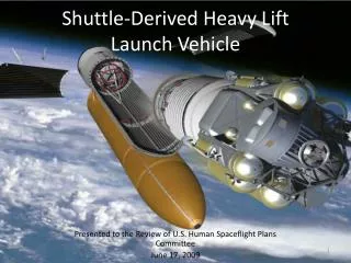
Heavy Lift Vehicle Configurations 4 Aug 2011
SLS Evolution Path Payload (mT) 50 60 70 80 90 100 110 120 130 FSB 5 SSME Std ET 2 J-2X-285 FSB 5 SSME Stretched ET 1 J-2X US Add US FSB 3 SSME Standard ET No upper stage FSB 4 SSME Standard ET No upper stage FSB 4 SSME Stretch ET No upper stage HLV HLV HLV
DM-3 Evolution and Applicability Payload (mT) 50 60 70 80 90 100 110 120 130 Space Shuttle FSB 5 SSME Std ET 2 J-2X-285 Ares I Existing Hardware & Current Contracts DM-3 Liberty FSB 5 SSME Stretched ET 1 J-2X US • DM-3 provides directly applicable technology maturation for next generation systems • DM-3 static test is the third in a critical series of motor tests to evolve and confirm the final Ares First Stage configuration • DM-3 provides significant risk mitigation for new motor features and satisfies 35 specific design objectives Add US FSB 3 SSME Standard ET No upper stage FSB 3 SSME Standard ET No upper stage FSB 4 SSME Standard ET No upper stage FSB 4 SSME Stretch ET No upper stage HLV HLV HLV
DM-3 Major Test Objectives Motor Objectives Critical Assessments • Demonstrate compliance to ballistic performance requirements at a 90oF PMBT • Assess ballistic predictions with high aft segment mach number and erosive burning at the 90oF PMBT requirement • Assess reduced insulation thickness as it approaches the projected flight profile • Verify PBI-NBR field joint performance at the upper temperature requirement • Evaluate aft dome flow characteristics and effect on insulation and boot at the 90oF PMBT requirement • Verify nozzle erosion at the 90oF PMBT requirement • Verify nozzle bondline performance at the upper extreme temperature requirement • Evaluate FNR flat development and potential abnormal erosion • Assess performance of ENKA CCP in ply-lift prone locations • Evaluate nozzle contour change • Evaluate silica cowl performance • Metal Structural Integrity* • Redundant and Verifiable Seals* • Pressure and Temp on Joints • Joint Thermal Barrier • FJPS • Case Insulation Operational Integrity* • Case Insulation Thermal SF • Joint Insulation* • Stress Relief Flap* • Inhibitors* • Field Joint System* • Insulation Structural SF* • Igniter Insulation • Safe & Arm • Operational Pressure Transducers • PMBT* • Propellant Performance* • Bore Choking SF* • Propellant Structural SF* • Nozzle Vectoring • Flex Boot Vectoring Capability • Flex Boot Performance Factor • Throat Erosion • Nozzle Flame Front Liner Erosion • Nozzle Primary Structural Elements • Nozzle Phenolics Structural SF • Nozzle Pre-loaded Bolts • Geometric Angular Alignment and Radial Offset • Nozzle Barrier • TVC System • Actuator Last Commanded Position • Shock and Vibration • TVA Temperatures • DFI • Forward Test Stand * Objectives apply to more than one segment Overview