Download
1 / 52
520 likes | 712 Vues
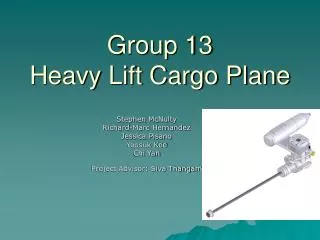
Group 13 Heavy Lift Cargo Plane. Stephen McNulty Richard-Marc Hernandez Jessica Pisano Yoosuk Kee Chi Yan Project Advisor: Siva Thangam. Overview. Objectives Schedule/Progress Design Concepts and Analysis Airfoil Fuselage Tail Landing Gear End of Semester Deliverables

E N D
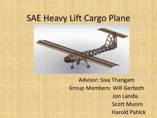
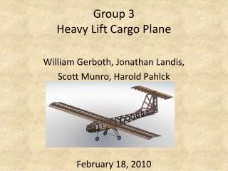
Group 13 Heavy Lift Cargo Plane Stephen McNulty Richard-Marc Hernandez Jessica Pisano Yoosuk Kee Chi Yan Project Advisor: Siva Thangam
Overview • Objectives • Schedule/Progress • Design Concepts and Analysis • Airfoil • Fuselage • Tail • Landing Gear • End of Semester Deliverables • Next Semester Goals
Objectives • Competition Specs are not posted for 2004 competition • The plane meets the specifications of the 2004 SAE Aero Design East/West competition • To finish the design of the plane by December and begin construction and testing in January • To compete well at competition and improve Stevens reputation • For the team to improve and expand their knowledge of the design and construction of airplanes
Journal/Progress • Researched airfoil computer analysis software • Calculations for Airfoil • Competition rules keep changing and are no longer posted on website • Stereo-lithography Lab • Landing Gear models and analysis • Fuselage Design and Calculations • Tail Design
Airfoil • Low camber, low drag, high speed, thin wing • Deep camber, high lift, low peed, thick wing • Deep camber, high lift, low speed, thin wing • Low lift, high drag, reflex trailing edge • Symmetrical (cambered top and bottom)
Airfoil • Airfoils used from previous years: • Year 2000: E 211 • Year 2001: E 423 • Year 2002: OAF 102 • From research: • E 214 • S 1223
Wing Shape • Rectangular • Tapered • Rounded (or Elliptical) • Swept Wing • Delta Wing
Wing Shape Comparison Rectangular Wing • Advantages: • Greater aileron control • East to construct • Disadvantages: • Not efficient in terms of stall and drag Tapered Wing • Advantages: • Decrease drag / Increase lift • Harder to construct • Disadvantages: • Not as efficient in terms of stall and drag
Wing Shape Comparison Elliptical Wing • Advantages: • Minimum drag • Most efficient compared to rect. and tapered • Disadvantages: • Hardest to construct Swept and Delta Wings • Advantages: • Minimum drag in high speed • Very stable and flexible • Disadvantages: • Suitable only for high speed aircrafts
Dihedral angle • Dihedral Wing • Flat Wing • Cathedral Wing • Gull Wing
Wing Angle Comparison Dihedral Wing • Advantages: • Helps stabilize aircraft motion from side to side • Helps stabilize aircraft motion when turning • Disadvantages: • Stress concentration at wing roots • Harder to construct Flat Wing • Advantages: • Easy to construct • Load distribution is equally spread out the wing • Disadvantages: • Not as stable as dihedral wings
Wing Angle Comparison Cathedral Wing • Advantages: • Helps stabilize aircraft motion from side to side • Helps stabilize aircraft motion when turning • Disadvantages: • Stress concentration at wing roots • Harder to construct • Suitable for high speed cargo planes Gull Wing • Advantages: • Helps stabilize aircraft motion from side to side • Helps stabilize aircraft motion when turning • Disadvantages: • Stress concentration at the Gull point • Hardest to construct • Suitable for high speed aircrafts
Number of Wings • Monoplane • Biplane • Triplane
Number of Wings Comparison Monoplane • Advantages • Easiest to construct • Very light weighted compared to Bi- and Tri-planes • Disadvantages • Produces less lift for the aircraft • Less stable when turning Biplane • Advantages • Adds more lift to the aircraft • More stable when turning • Disadvantages • Harder to construct and repair • Adds more weight to the aircraft Triplane • Advantages • Produces highest lift for aircraft • Most stable compared to Mono- and Bi-planes • Disadvantages • Hardest to construct and repair • Adds more weight to the aircraft
Number of Wings Matrix • Currently do not have one yet • 2004 Aero East Design rules are not up • Decision is made based upon on the rules and regulations of the competition
Selection • Selig 1223 • Rectangular • Dihedral
Fuselage • Panels • Wireframe • Cast Mold • Injection Mold
Fuselage Comparison Cons: • Not very strong Panels Pros: • Lightweight • Easy to construct • Easy to assemble • Affordable
Fuselage Comparison Cons: • Heavy • Difficult to construct Wire frame Pros: • Very Strong and sturdy • Affordable
Fuselage Comparison Cons: • unaffordable • Difficult to design a mold • No spare parts Cast Molding Pros: • Very accurate shape • Aerodynamic advantages • Strong frame • No assembly required
Fuselage Comparison Cons: • Unaffordable • Heavy • Difficult to design a mold • No spare parts Injection Molding Pros: • Very accurate shape • Aerodynamic advantages • Strong frame • No assembly required
Selection Panel Fuselage
Tail Boom • 1 spar • 2 spars • 3 spars • 3 or more panels
Selection Three Spar
Landing Gear Analysis • SolidWorks models • Deflection Analysis • Stress Analysis • Deformation Analysis • Top fixed • Force applied to bottom of legs • Force applied = 45lbs • Force = Weight of plane
Landing Gear Design 1 Analysis • Standard Main Landing Gear • Aluminum • Max Deflection .2238 in • Design Rejected • Stress Max 6.162e3 Psi
Landing Gear Design 2 Analysis • Max Deflection .0196 in • Stress Max 1.651 Psi • Main Landing Gear with Rod • Aluminum • Last years final design
Landing Gear Design 3Analysis • Max Deflection 1.841e-3 in • Stress Max 6.783e+2 Psi • Main Landing Gear • Truss Design • Aluminum • Design Being Strongly Considered
Landing Gear Design 4Analysis • Max Deflection 1.342e-3 in • Stress Max 5.332e+2 Psi • Main Landing Gear • Modified Truss Design • Aluminum • Design Being Strongly Considered
Landing Gear Design 5Analysis • Max Deflection 1.890e-4 in • Stress Max 2.651e+2 Psi • Main Landing Gear • Modified Truss Design • Modified for Lighter Weight • Aluminum • Selected
Tail Design and Calculations • Tail stabilizer does not provide lift to plane. • Symmetrical airfoil is needed for vertical tail.
Tail • Vertical Tail Stabilizer • 2ft • controls the horizontal movement of plane • keeps the nose of the plane from swinging from side to side • Horizontal Tail Stabilizer • 3.33ft • controls vertical movement of plane • prevents an up-and-down motion of the nose
Construction • Wing/Tail Construction • Foam Core • Risers (Balsa Wood) • Fuselage Construction • Plywood • Aluminum Plate • Boom Construction • Wooden Dowels • Carbon Fiber Tubes • Plywood • Landing Gear • Aluminum • Steel • Tire • Rubber Core • Air Filled Rubber • Sponge
ME 423 Senior Design, Fall 2003. Project Number 13Team members: R. Hernandez, Y. Kee, S. McNulty, J. Pisano, C. Yan Advisor: Professor Siva Thangam Title:Creation of a Heavy Lift Radio-Controlled Cargo Plane • Design a high performance heavy lift R/C cargo plane whose purpose is to carry the most weight possible • Enter manufactured design into 2004 SAE Aero Design East Competition in Orlando, FL • Carbon Fiber Spars connecting fuselage and tail • S1223 airfoil • balsa wood risers construction of stabilizers and wings • Rectangular wing planform • Horner plates (winglets) for improved flight characteristics • Tail dragger landing gear configuration • Unitized body fuselage • Dihedral Wing • Technology • Utilization of the latest airfoil simulations, composite materials, to obtain the lightest design that creates the most lift • Maximum lift • Selection of airfoil and wing shape • Light materials • Drag reduction • Wingspan: 10ft • Engine: FX OS 2 stroke motor • 0.61 cubic inches 1.9 hp • Minimum Cargo Area: 120 in3 • Cargo Weight: 35 pounds • Empty Plane Weight: 10 pounds • Plane Length: 7.5ft • Plane Height: 1 ft
End of Semester Deliverables • Completed Airplane design • Calculations • CAD models and analyses • Completed parts list for plane construction • Gantt Chart for spring semester • Budget