Download
1 / 17
190 likes | 481 Vues
SAE Heavy Lift Cargo Plane. Advisor: Siva Thangam Group Members: Will Gerboth Jon Landis Scott Munro Harold Pahlck. Presentation Outline. Project Objectives Design Specifications Comments Addressed

E N D
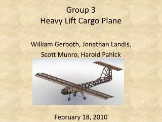
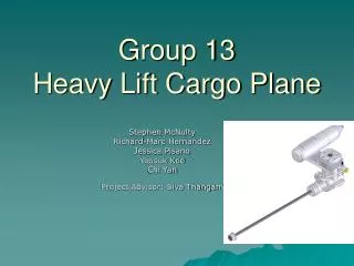
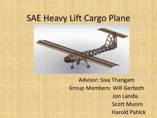
SAE Heavy Lift Cargo Plane Advisor: Siva Thangam Group Members: Will Gerboth Jon Landis Scott Munro Harold Pahlck
Presentation Outline • Project Objectives • Design Specifications • Comments Addressed • Construction Methods • Major Issues • Performance Testing Plan • Build Schedule • Budget • Deliverables • Nugget Chart • E Poster
Project Objectives • Design and build an airplane that meets the requirements of the SAE Aero East competition • Plane must successfully take off from a runway of 200 feet and land on a runway 400 feet • Constraints of 55 pounds total weight, and the combined height, length, and width of 200 inches • Plane must make one complete 360° circuit of the field per attempt
Design Specifications • Wing span of 120 inches • Overall length of 60 inches • Height of 20 inches • Maximum lifting capacity – 25 pounds • Airfoil Shape: Eppler 423 • 32 short ribs, 6 long ribs to support flaps and ailerons • 3 spars support wingspan • Landing Gear: Tricycle • Pre-fabricated Aluminum • Tail shape: T-Tail • Horizontal tail • 12 ribs, NACA 0012 airfoil
Comments Addressed • Where does the 30% for servos come from? • The author of the calculation used suggests that 30% is added to account for inertial forces and other empirical “tweaking” • There seems to be a large discrepancy between the torques calculated? • The two methods provide similar numbers except for the rudder. The larger number was chosen for the rudder because that servo also needs to turn the front wheel
Comments Addressed • Why does the assembly need to be done in series? • The group first thought it would be better to have everyone work on the same part, but has now realized that some people are better suited to different parts and can become more efficient • Are there any precautions that need to be taken to ensure that wiring doesn’t become tangled? • Wires will be wired to servos individually and zip tied to the plane
Comments Addressed • Is it necessary to do this calculation for larger weights that may be added as well? • The group did the equation for several weights and the more weight that was added, the center of gravity moved further in front of the neutral point, making the plane more stable
Construction Methods • Fuselage • 1:1 Scale drawings made using SolidWorks • Plotter printer used to print large dimension drawings • Drawings cut out and used as templates • 48 in x 6 in x 1/8 in balsa wood sheet cut using X-acto knives • Balsa joined with epoxy • ¼ in. plywood fuselage floor cut using band saw • ½ in. holes drilled with drill press to reduce weight
Construction Methods • Wing • Ribs cut from 3/32 in. balsa sheets • Template used to ensure proper dimensions • Ribs will be attached to 3 spars of various dimensions • Ribs will be glued to leading edge, trailing edge, mid-chord spars to give wing rigidity and strength • Tail • Will be made of individual square sticks glued together • Leading edge will be rounded for better aerodynamics • Horizontal tail created similar to the wing
Construction Methods • Landing Gear • Salvaged from previous year’s plane • Rear Landing Gear will be bolted to t-nuts located in plywood fuselage floor • Front Landing Gear will be bolted to t-nuts in plywood firewall • Servo arm attached to front landing gear to allow for steering
Major Issues • Balsa wood is difficult to cut due to splitting. • Pieces had to be redone, wasting time and material • When cutting against the grain, multiple passes were required with an X-acto knife • Large scale plotter printer failed • Additional printers required TIF file but Solidworks does not support in high resolution • Initial wood came in warped
Performance Testing Plan • Locate actual center of gravity • Flaps, ailerons, elevators, and rudders move correctly with servos coordinating with controller. • Takeoff must occur within 200 feet • Landing in no more than 400 feet • Must complete 360 degree circuit in the air • Plane must be stable and easily controllable • Engine does not overheat • Landing gear withstands impact • Battery and fuel must be sufficient to complete circuit
Deliverables • Complete aircraft construction by April 9th • Have completed and tested plane ready for Senior Design Day April 28th • Testing results • Final payload • Provide video of flight tests