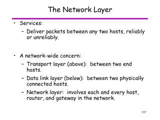
Layering and the network layer
350 likes | 594 Vues
Layering and the network layer. CS168, Fall 2014 Sylvia Ratnasamy http://inst.eecs.berkeley.edu/~cs168/fa14/. Today. What is a network made of? How is it shared? How do we evaluate a network? How is communication architected? BREAK The network layer. Physical. Network. Application.

Layering and the network layer
E N D
Presentation Transcript
Layering and the network layer CS168, Fall 2014Sylvia Ratnasamyhttp://inst.eecs.berkeley.edu/~cs168/fa14/
Today • What is a network made of? • How is it shared? • How do we evaluate a network? • How is communication architected? • BREAK • The network layer
Physical Network Application Transport Data link Internet Layers Applications …built on… Reliable (or unreliable) transport L7 …built on… L4 Best-effort global packet delivery L3 …built on… L2 Best-effort local packet delivery L1 …built on… Physical transfer of bits
Physical Physical Network Network Application Application Transport Transport Data link Data link Protocols and Layers Communication between peer layers ondifferent systems is defined by protocols L7 L7 L4 L4 L3 L3 L2 L2 L1 L1
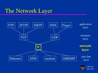
Physical Network Application Transport Data link Ethernet FDDI optical PPP DNS UDP HTTP SMTP NTP TCP IP radio copper PSTN Protocols at different layers There is just one network-layer protocol! L7 L4 L3 L2 L1
Physical Physical Network Network Application Application Transport Transport Data link Data link What gets implemented where? L7 L7 L4 L4 L3 L3 L2 L2 L1 L1
What gets implemented at the end systems? • Bits arrive on wire, must make it up to application • Therefore, all layers must exist at host!
What gets implemented in the network? • Bits arrive on wire physical layer (L1) • Packets must be delivered across links and local networks datalink layer (L2) • Packets must be delivered between networks for global delivery network layer (L3) • The network does not support reliable delivery • Transport layer (and above) not supported
Application Application Simple Diagram • Lower three layers implemented everywhere • Top two layers implemented only at hosts Transport Transport Network Network Network Datalink Datalink Datalink Physical Physical Physical End system Switch End system
A closer look: end-system • Application • Web server, browser, mail, game • Transport and network layer • typically part of the operating system • Datalink and physical layer • hardware/firmware/drivers
What gets implemented in the network? • Bits arrive on wire physical layer (L1) • Packets must be delivered across links and local networks datalink layer (L2) • Packets must be delivered between networks for global delivery network layer (L3) • Hence: • switches: implement physical and datalink layers (L1, L2) • routers: implement physical, datalink, network layers (L1, L2, L3)
A closer look: network link switch Internet Service Provider
A closer look: network link routers switch switch Internet Service Provider
Switches vs. Routers • Switches do what routers do but don’t participate in global delivery, just local delivery • switches only need to support L1, L2 • routers support L1-L3 • Won’t focus on the router/switch distinction • when I say switch, I almost always mean router • almost all boxes support network layer these days
msg App msg Ht Ht msg msg Transport Hn Hn Hn Ht Ht Ht msg msg msg Network Link Hl Hl Hl Hl Hn Hn Hn Hn Ht Ht Ht Ht msg msg msg msg Physical Alice Router Bob
Logical Communication • Layers interacts with peer’s corresponding layer Application Application Transport Transport Network Network Network Datalink Datalink Datalink Physical Physical Physical Host A Router Host B
Application Application Physical Communication • Communication goes down to physical network • Then up to relevant layer Transport Transport Network Network Network Datalink Datalink Datalink Physical Physical Physical Host A Router Host B
IP IP IP Ethernet interface A Protocol-Centric Diagram host host HTTP message HTTP HTTP TCP segment TCP TCP router router IP packet IP packet IP packet IP Ethernet interface SONET interface Ethernet interface Ethernet interface SONET interface
Why layers? • Reduce complexity • Improve flexibility
Why not? • sub-optimal performance • cross-layer information often useful • several “layer violations” in practice
What physical infrastructure is already available? • Reserve or on-demand? • Where’s my delay coming from? • What’s the right set of layers?
Physical Network Application Transport Data link Ethernet FDDI optical PPP DNS UDP HTTP SMTP TCP NTP IP radio copper PSTN Backing up… Why is this architecture good? L7 at ends L4 L3 In network L2 L1
Architectural Wisdom • Benefits of layering • reduce complexity, increase flexibility • “narrow waist” • simple, minimal requirements for interoperability • “smart ends, dumb network” • No application knowledge in network more general • Minimal state in the network more robust to failure
Architectural Wisdom • David D. Clark (MIT) • Chief protocol architect for the Internet from 1981 • Co-authored two classics • “End-to-End Arguments in System Design” (1981) • “The Design Philosophy of the DARPA Internet Protocols” (1988)
OK Example: Reliable File Transfer • Solution 1: make each step reliable, and string them together to make reliable end-to-end process • Solution 2: end-to-end check and retry Host A Host B App App OS OS
Discussion • Solution 1 is incomplete • What happens if any network element misbehaves? • Receiver has to do the check anyway! • Solution 2 is complete • Full functionality can be entirely implemented at application layer with no need for reliability from lower layers
End-to-end argument: Intuition • Some application requirements can only be correctly implemented end-to-end • reliability, security, etc. • Implementing these in the network is hard • every step along the way must be fail proof • End-systems • Can satisfy the requirement without network’s help • Will/must do so, since they can’t rely on the network
End-to-End Arguments in Clark’s words “The function in question can completely and correctly be implemented only with the knowledge and help of the application at the end points of the communication system. Therefore, providing that function as a feature of the communication system itself is not possible. (Sometimes an incomplete version of the function provided by the communication system may be useful as a performance enhancement.)”
Recap • Implementing functionality (e.g., reliability) in the network • Doesn’t reduce host implementation complexity • Does increase network complexity • Decreases generality (of the network) • However, implementing functionality in the network can improve performance in some cases • e.g., consider a very lossy link
Commonly used examples • Error handling in file transfer • End-to-end, versus in-network encryption • The partition of work between TCP and IP forreliable packet delivery • What about Quality of Service (QoS)? • Communication throughput or delay guarantee
Some consequences • In layered design, the E2E principle provides guidance on which layers are implemented where • “Dumb”network and “smart” end systems • Often credited as key to the Internet’s success • “Fate sharing” • Store state at the system entities that rely on the state • Often translated to keeping state out of routers
Cracks in the E2E argument? • Ignores incentives of different stakeholders • e.g., ISP looking for new revenue-generating services • e.g., users looking for a performance boost • Sometimes we don’t trust the end-systems to do the job • e.g., firewalls, intrusion detection systems
Recap: architectural decisions • How to break system into modules? • Classic decomposition into tasks • Where are modules implemented? • Hosts? Routers? Both? • Where is state stored? • Hosts? Routers? Both?
Leads to three guiding principles • How to break system into modules? • Layering • Where are modules implemented? • End-to-end principle • Where is state stored? • Fate-sharing