Download

1 / 64
670 likes | 914 Vues
An Introduction to Radar and Lidar Remote Sensing. Credit to: Weile Wang. With materials from Drs. Jeff Dozier (UCSB), Howard Zebker (Stanford), Jacob van Zyl (JPL), Alan Strahler (Boston U.), Ralph Dubayah (U. Maryland), Michael Lefsky (U. Colorado), Guoqing Sun (U. Maryland), and many others.

E N D
An Introduction to Radar and Lidar Remote Sensing Credit to: Weile Wang With materials from Drs. Jeff Dozier (UCSB), Howard Zebker (Stanford), Jacob van Zyl (JPL), Alan Strahler (Boston U.), Ralph Dubayah (U. Maryland), Michael Lefsky (U. Colorado), Guoqing Sun (U. Maryland), and many others. Gustav Klimt (1862-1918), Der Park
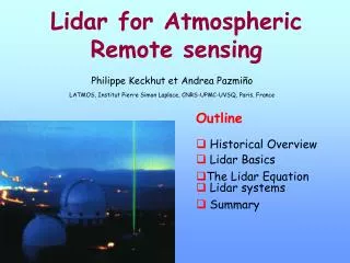
Outline • Radar Basics, PPI, SLAR, SAR, InSAR; • Radar Equation, Imaging Geometry, Geometric Distortion, Speckle, Polarization, Interferometry; • Lidar, Waveform, Footprint, Forest Structure Measurement; • SRTM, LVIS, SMAP, GRACE, DESDynI, and Echidna.
Active and passive remote sensing • Passive: uses natural energy, either reflected sunlight or emitted thermal or microwave radiation • Active: sensor creates its own energy • Transmitted toward Earth • Interacts with atmosphere and/or surface • Reflects back toward sensor (backscatter)
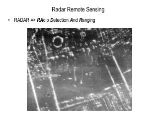
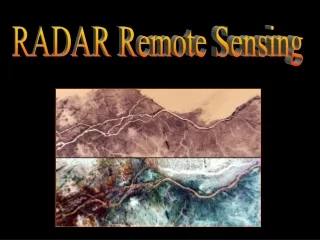
Common active remote sensing systems • Radar (RAdio Detection And Ranging) • long-wavelength microwaves (1-100cm) • recording the amount of energy back-scattered from the terrain • Lidar (LIght Detection And Ranging) • short-wavelength laser light (e.g., 0.90 µm) • recording the light back-scattered from the terrain or atmosphere • Sonar (SOund Navigation And Ranging) • sound waves through a water column • recording the amount of energy back-scattered from the water column or the bottom
What is Radar? • RADAR = Radio Detection And Ranging • Since radar pulses propagate at the speed of light, the difference to the “target” is proportional to the time it takes between the transmit event and reception of the radar echo
Ranging: Distance Measurement ? ? c = speed of light = 3.00 × 10⁸ m/s
Mapping Multiple Objects: PPI Radar Display PPI=Plan Position Indicator
The Radar Equation (1) • Gt is the “Antenna Gain”; • σ is the “cross section” of the target.
The radar equation (2) The radar equation represents the physical dependences of the transmit power, that is the wave propagation up to the receiving of the echo-signals. The power PE returning to the receiving antenna is given by the radar equation, depending on the transmitted power Pt, the slant range R, and the reflecting characteristics of the aim (described as the radar cross-section σ). At known sensibility of the radar receiver the radar equation determines the achieved by a given radar set theoretically maximum range. Furthermore one can assess the performance of the radar set with the radar equation. Suggest reading: http://www.radartutorial.eu/01.basics/rb13.en.html
The radar equation (3) antenna gain: Since a spherical segment emits equal radiation in all direction (at constant transmit power), if the power radiated is redistributed to provide more radiation in one direction, then this results an increase of the power density in direction of the radiation. This effect is called antenna gain.
Imaging Geometry azimuth refers to the along-track dimension parallel to the flight direction. Swath width refers to the strip of the Earth’s surface from which data are collected by a side-looking airborne radar (SLAR)
Radar Reflections from Flat Ground The Earth plane surrounding a radar antenna has a significant impact on the vertical polar diagram. The combination of the direct and re-reflected ground echo changes the transmitting and receiving patterns of the antenna.
Nomenclature • nadir • azimuth flight direction • look direction • range (near and far) • depression angle (γ) • incidence angle (θ) • altitude above-ground-level, H • polarization
Range resolution Calculate Rr
Side-looking airborne radar (SLAR) H is the height of the antenna, (height of the airplane)L is the geometric length of the antenna,λ is the wavelength of the transmitted pulses, andθ is the incidence angle(1) L · cos θ
Azimuth resolution Question: Why is wavelength important in determining Ra?
The equation shows, that with increasing altitude decreases the azimuthal resolution of SLAR. A very long antenna (i.e., large L) would be required to achieve a good resolution from a satellite. Synthetic Aperture Radar (SAR) is used to acquire higher resolution.
For an SLAR with the following characteristics:λ = 1 cm,L = 3 m,H = 6000 m,θ = 60°, andtp = 100 ns,has got a resolution ofRa = ??? andRr = ??? m • Note: The same SLAR on a platform in a height of 600 km would achieve an azimuth-resolution of Ra = ???.
A Synthetic Aperture Radar (SAR), or SAR, is a coherent mostly airborne or spaceborne sidelooking radar system which utilizes the flight path of the platform to simulate an extremely large antenna or aperture electronically, and that generates high-resolution remote sensing imagery. • Read http://www.radartutorial.eu/20.airborne/ab07.en.html
The SAR works similar of a phased array, but contrary of a large number of the parallel antenna elements of a phased array, SAR uses one antenna in time-multiplex. The different geometric positions of the antenna elements are result of the moving platform now. • The SAR-processor stores all the radar returned signals, as amplitudes and phases, for the time period T from position A to D. Now it is possible to reconstruct the signal which would have been obtained by an antenna of length v · T, where v is the platform speed. As the line of sight direction changes along the radar platform trajectory, a synthetic aperture is produced by signal processing that has the effect of lengthening the antenna. Making T large makes the „synthetic aperture” large and hence a higher resolution can be achieved. • As a target (like a ship) first enters the radar beam, the backscattered echoes from each transmitted pulse begin to be recorded. As the platform continues to move forward, all echoes from the target for each pulse are recorded during the entire time that the target is within the beam. The point at which the target leaves the view of the radar beam some time later, determines the length of the simulated or synthesized antenna. The synthesized expanding beamwidth, combined with the increased time a target is within the beam as ground range increases, balance each other, such that the resolution remains constant across the entire swath. • The achievable azimuth resolution of a SAR is approximately equal to one-half the length of the actual (real) antenna and does not depend on platform altitude (distance).
Geometric Distortions (or: Slant-range distortion) • Foreshortening • Layover • Shadow See handout
Slant-range distortion The slant-range distortion occurs because the radar is measuring the distance to features in slant-range rather than the true horizontal distance along the ground. This results in a varying image scale, moving from near to far range. Foreshortening occurs when the radar beam reaches the base of a tall feature tilted towards the radar (e.g. a mountain) before it reaches the top. Because the radar measures distance in slant-range, the slope (from point a to point b) will appear compressed and the length of the slope will be represented incorrectly (a' to b') at the image plane. Layover occurs when the radar beam reaches the top of a tall feature (b) before it reaches the base (a). The return signal from the top of the feature will be received before the signal from the bottom. As a result, the top of the feature is displaced towards the radar from its true position on the ground, and „lays over” the base of the feature (b' to a'). The shadowing effect increases with greater incident angle θ, just as our shadows lengthen as the sun sets.
Layover • Extreme case of foreshortening, when incidence angle is less than slope angle toward radar (i.e. θ<α) • cannot be corrected • got to be careful in the mountains
Shadow • When slope away from radar is steeper than the depression angle, i.e. –α > γ
Speckle: Random Interference • Grainy salt-and-pepper pattern in radar imagery • Caused by coherent nature of the radar wave, which causes random constructive and destructive interference, and hence random bright and dark areas in a radar image • Reduced by multiple looks • processing separate portions of an aperture and recombining these portions so that interference does not occur
Sources of radar backscattering from a vegetation canopy Question: Does the strength of the backscattering vary with frequencies?
Strength of scattering from a pine stand depends on frequency
Polarization • 1st letter is transmitted polarization, 2nd is received • Can have VV, HH (like) • HV, VH (cross)
Polarization with radar • RADARSAT, C-band radar (5.4 GHz) with HH, VV, HV, and VH polarizations
InSAR: Adding the Z-dimension Landsat overlaid on topography from SRTM – Malaspina Glacier, Alaska
InSAR Geometry Can you derive the equation? Extra credit (point)
Shuttle Radar Topography Mission Links to movies
SRTM Elevation + Landsat Imagery Perspective with Landsat Overlay: Antelope Valley, California
From Radar to Lidar • LIDAR = LightDetection And Ranging • Using laser instead of microwave