
Flame Rectification
E N D
Presentation Transcript
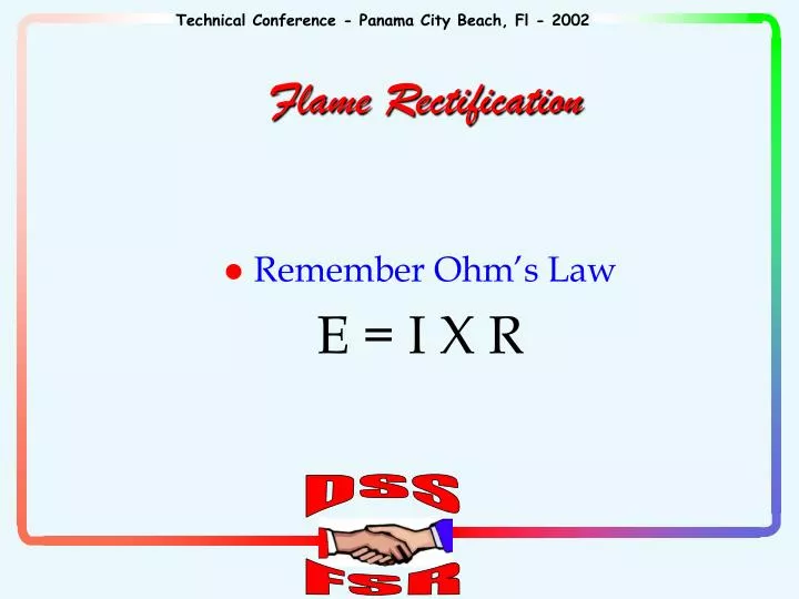
Remember Ohm’s Law E = I X R Flame Rectification
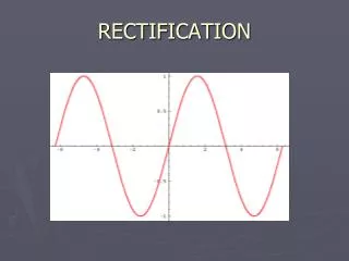
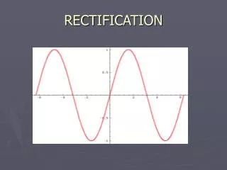
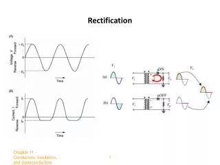
Alternating Current Sine Wave + + + Applied AC voltage - -
SOURCE - + CONDUCTOR CONTROL LOAD Basic Electrical Circuit
What devices are used for electrodes? Flame rod Burner Flame Rectification circuit!
The Voltage Source is the Ignition Control The “load” is the flame sensing circuit inside the control The conductors are the electrodes already identified. What acts as the “switch”? The flame completes the circuit. Flame Rectification Circuit
One electrode is larger than the other causing electron flow to be greater in one direction than in the other. Compare the burner size to the flame rod size. Flame Sense Circuit
+ F G _ Current flow when flame rod is positive 5a + 0 -
_ F G + Current flow when flame rod is negative 1a + 0 -
Effective Flame Signal + + a Effect = 4a pulsating DC Applied AC voltage a - -
Remember Ohm’s Law ? What happens in a circuit if resistance increases and voltage stays the same? Flame Rectification Circuit
Need to measure AC A as well as DC A Typical in-shot burner DC current is 2-5 A with a 4-8 A AC leakage. DC current is less than 1 A and AC current is at or above 4A1. Flame signal is weak2. Corrective action is required Typical Flame Detection Current
DC Current vs. AC Current DC CURRENT AC CURRENT AC DROPOUT 0.5 3.94 10.39 1.0 4.37 17.28 1.5 4.88 20.1 2.0 5.45 20.30 2.5 6.20 24.37 3.0 6.95 24.20 3.5 8.29 24.22
Remember Ohm’s Law ? What happens in a circuit if resistance increases and voltage stays the same? What can affect the resistance in the circuit? What else can affect the flame signal? Flame Rectification Circuit
Burner oxidation Non-secure burner Flame “lift off” Loose wire connections Contaminated flame sensor Faulty grounds No grounds Reverse polarity Increased circuit resistances